8 Connection
8.1 Transducers PIOX S72*
2022-05-15, UMPIOX_S72xV1-9EN
68
8.1 Transducers
It is recommended to run the cables from the measuring point to the transmitter before connecting the transducers to
avoid load on the connectors.
8.1.1 Connection of the transducer cable to the transmitter
8.1.1.1 Transducer cable with SMB connectors
• Remove the blind plug for the connection of the transducer cable.
• Insert the transducer cable with the SMB connectors into the housing.
• Fix the transducer cables by tightening the cable glands.
• Connect the SMB connectors to the sockets of the transmitter.
If transducers are replaced or added, the SENSPROM has to be replaced or added as well.
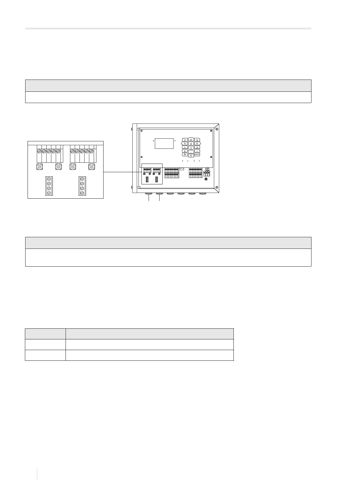
Fig. 8.1: Connection of the transducers to the transmitter
1 – transducers (measuring channel A)
2 – transducers (measuring channel B)
The degree of protection of the transmitter is only ensured if all cables are tightly fitted using cable glands and the
housing is firmly screwed.
Tab. 8.1: Terminal assignment
terminal connection
X_AV SMB connector (brown cable, marked white)
X_AR SMB connector (brown cable, marked black)
A
B
SNAP
DISP
DISP
MODEFAST
MUX
NEXT
Q
ON
Q+Q-
3x Q
OFF
LAN
USB
A+
B-
P1+
P2+
P3+
P4+
P5a
P6a
P7a
S
S
P1-
P2-
P3-
P4-
P5b
P6b
P7b
X2 X3
X_AV
KL11
KL12
KL7KL8
KL9KL10
KL4
X_AR X_BV X_BR
T1A
T1B
S1
T2A
T2B
T3A
T3B
S3
T4B
T4A
T1a
T1b
S1
T2a
T2b
T3a
T3b
S3
T4b
T4a
N(-)
PE
L(+)
AV
AVS
AGN
ARS
AR
BV
BVS
BGN
BRS
BR
X2 X3
X_AV X_AR X_BV X_BR
AV
AVS
AGN
ARS
AR
BV
BVS
BGN
BRS
BR