8 Connection
8.3 Outputs PIOX S72*
2022-05-15, UMPIOX_S72xV1-9EN
82
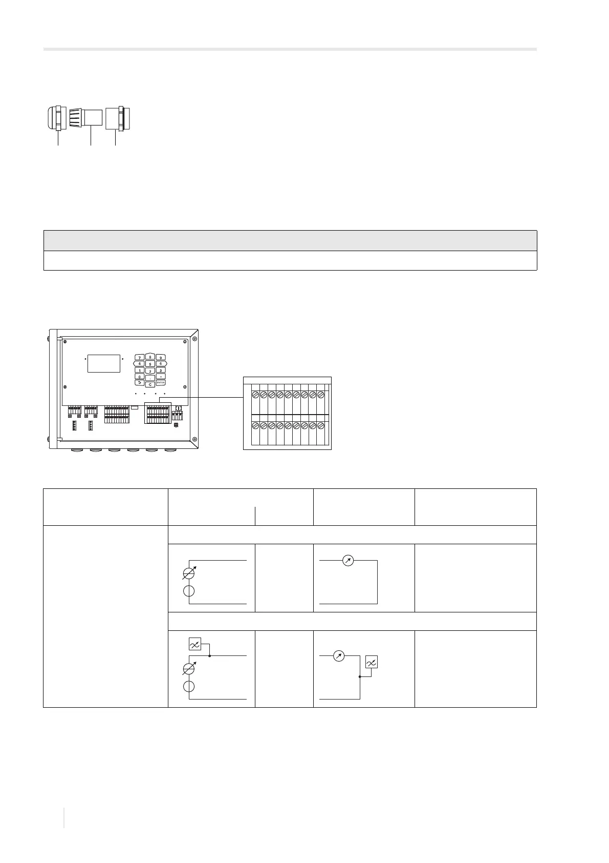
8.3 Outputs
• Connect the output cable to the transmitter (see 8.2.1, Fig. 8.16 and Tab. 8.11).
Fig. 8.15: Cable gland for aluminum housing
1 – cap nut
2 – compression part
3 – basic part
The max. permissible voltage between the outputs and against PE is 60 V DC (permanent).
Fig. 8.16: Connection of the outputs to the transmitter
Tab. 8.11: Output circuits
output transmitter external circuit explanation
internal circuit connection
active current output/HART current output
U
int
= 24 V
R
ext
< 500 Ω
HART
U
int
= 24 V
R
ext
< 500 Ω
The number, type and connections of the outputs depend on the order.
R
ext
is the sum of all ohmic resistances in the circuit (e.g., resistance of the conductors, resistance of the ammeter/voltmeter).
A
B
SNAP
DISP
DISP
MODEFAST
MUX
NEXT
Q
ON
Q+Q-
3x Q
OFF
LAN
USB
A+
B-
P1+
P2+
P3+
P4+
P5a
P6a
P7a
S
S
P1-
P2-
P3-
P4-
P5b
P6b
P7b
X2 X3
X_AV
KL11
KL12
KL7KL8
KL9KL10
KL4
X_AR X_BV X_BR
T1A
T1B
S1
T2A
T2B
T3A
T3B
S3
T4B
T4A
T1a
T1b
S1
T2a
T2b
T3a
T3b
S3
T4b
T4a
N(-)
PE
L(+)
AV
AVS
AGN
ARS
AR
BV
BVS
BGN
BRS
BR
A+
B-
P1+
P2+
P3+
P4+
P5a
P6a
P7a
S
S
P1-
P2-
P3-
P4-
P5b
P6b
P7b
G