9 Start-up
PIOX S72* 9.3 Status indications
97
UMPIOX_S72xV1-9EN, 2022-05-15
9.3 Status indications
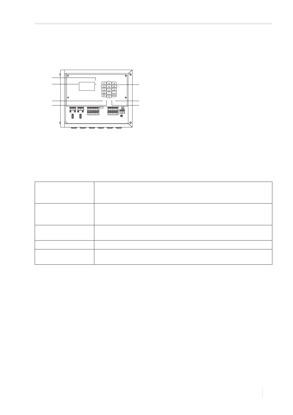
The operation state is indicated by LEDs.
Fig. 9.1: Command panel of the transmitter
1 – LED (channel A)
2 – LED (channel B)
3–keyboard
4 – LED LAN activity
5 – LED LAN mode
6 – LED USB device
7 – LED USB host (not used)
Tab. 9.1: Operation state of the transmitter
LED (channel A) Lights if the transmitter is in measuring mode and channel A is activated.
red – invalid measurement
green – valid measurement
LED (channel B) Lights if the transmitter is in measuring mode and channel B is activated.
red – invalid measurement
green – valid measurement
LED LAN activity Lights if the transmitter is connected to a network via USB cable.
Flashes in case of data exchange on the network connection.
LED LAN mode Lights if the data rate is 100 MBit/s otherwise it is 10 MBit/s.
LED USB device Lights if the transmitter is connected to a PC via USB cable.
Flashes in case of data exchange between PC and transmitter.
A
B
SNAP
DISP
DISP
MODEFAST
MUX
NEXT
Q
ON
Q+Q-
3x Q
OFF
LAN
USB
A+
B-
P1+
P2+
P3+
P4+
P5a
P6a
P7a
S
S
P1-
P2-
P3-
P4-
P5b
P6b
P7b
X2 X3
X_AV
KL11
KL12
KL7KL8
KL9KL10
KL4
X_AR X_BV X_BR
T1A
T1B
S1
T2A
T2B
T3A
T3B
S3
T4B
T4A
T1a
T1b
S1
T2a
T2b
T3a
T3b
S3
T4b
T4a
N(-)
PE
L(+)
AV
AVS
AGN
ARS
AR
BV
BVS
BGN
BRS
BR