8 Connection
8.2 Power supply PIOX S72*
2022-05-15, UMPIOX_S72xV1-9EN
80
8 Connection
8.2 Power supply
The installation of the power supply is carried out by the operator. The operator has to provide an overcurrent protector
(fuse or similar device) disconnecting all energizing wires in case of an inadmissible high current consumption. The
impedance of the protective earth has to be low ohmic in order not to allow touch voltage pass the permissible limit. The
equipotential bonding terminal serves as functional earth of the transmitter.
• Connect the power cable to the transmitter (see section 8.2.1, Fig. 8.13 and Tab. 8.10).
The degree of protection of the transmitter will only be guaranteed if the power cable fits firmly and tightly in the cable
gland.
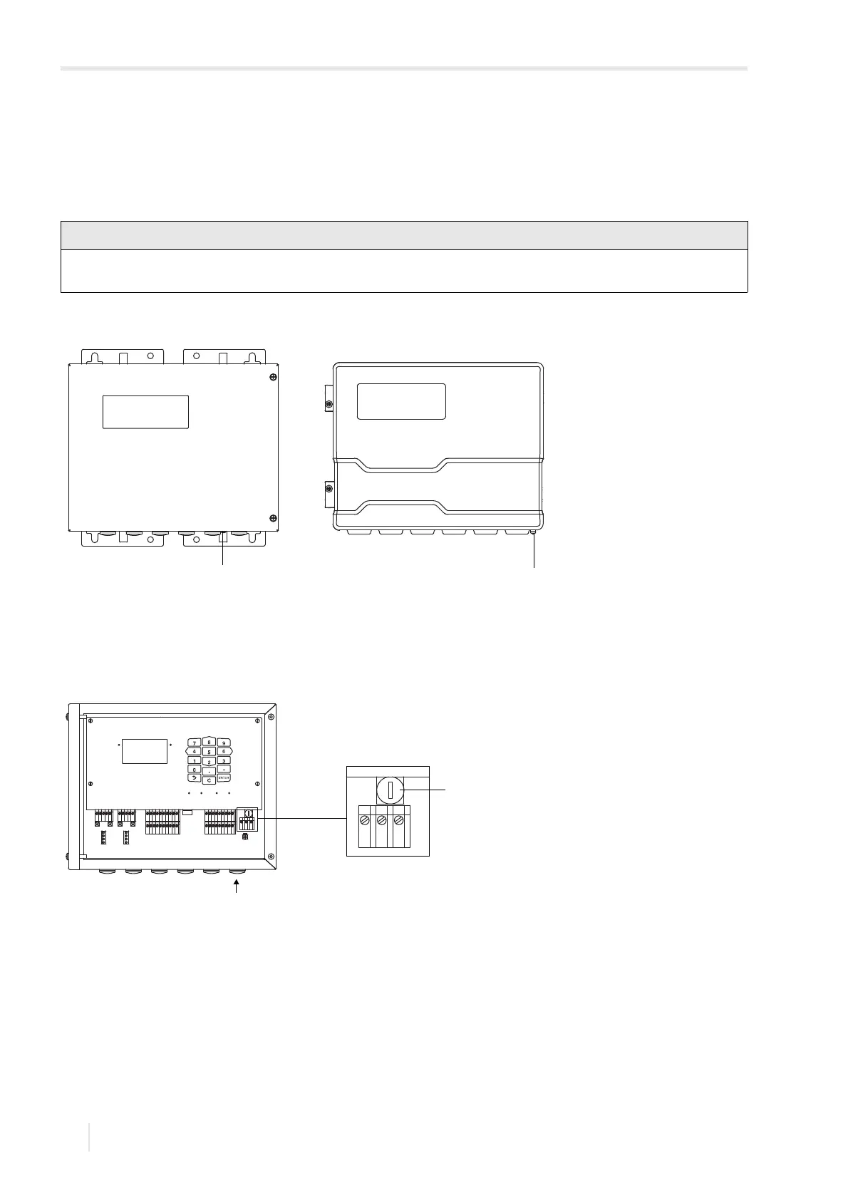
Fig. 8.12: Equipotential bonding terminal on the transmitter
1 – equipotential bonding terminal on stainless steel housing
2 – equipotential bonding terminal on aluminum housing
Fig. 8.13: Connection of the power supply to the transmitter
1–fuse
2 – connection of the power supply
A
B
SNAP
DISP
DISP
MODEFAST
MUX
NEXT
Q
ON
Q+Q-
3x Q
OFF
LAN
USB
A+
B-
P1+
P2+
P3+
P4+
P5a
P6a
P7a
S
S
P1-
P2-
P3-
P4-
P5b
P6b
P7b
X2 X3
X_AV
KL11
KL12
KL7KL8
KL9KL10
KL4
X_AR X_BV X_BR
T1A
T1B
S1
T2A
T2B
T3A
T3B
S3
T4B
T4A
T1a
T1b
S1
T2a
T2b
T3a
T3b
S3
T4b
T4a
N(-)
PE
L(+)
AV
AVS
AGN
ARS
AR
BV
BVS
BGN
BRS
BR