8 Connection
PIOX S72* 8.4 Inputs
85
UMPIOX_S72xV1-9EN, 2022-05-15
8.4 Inputs
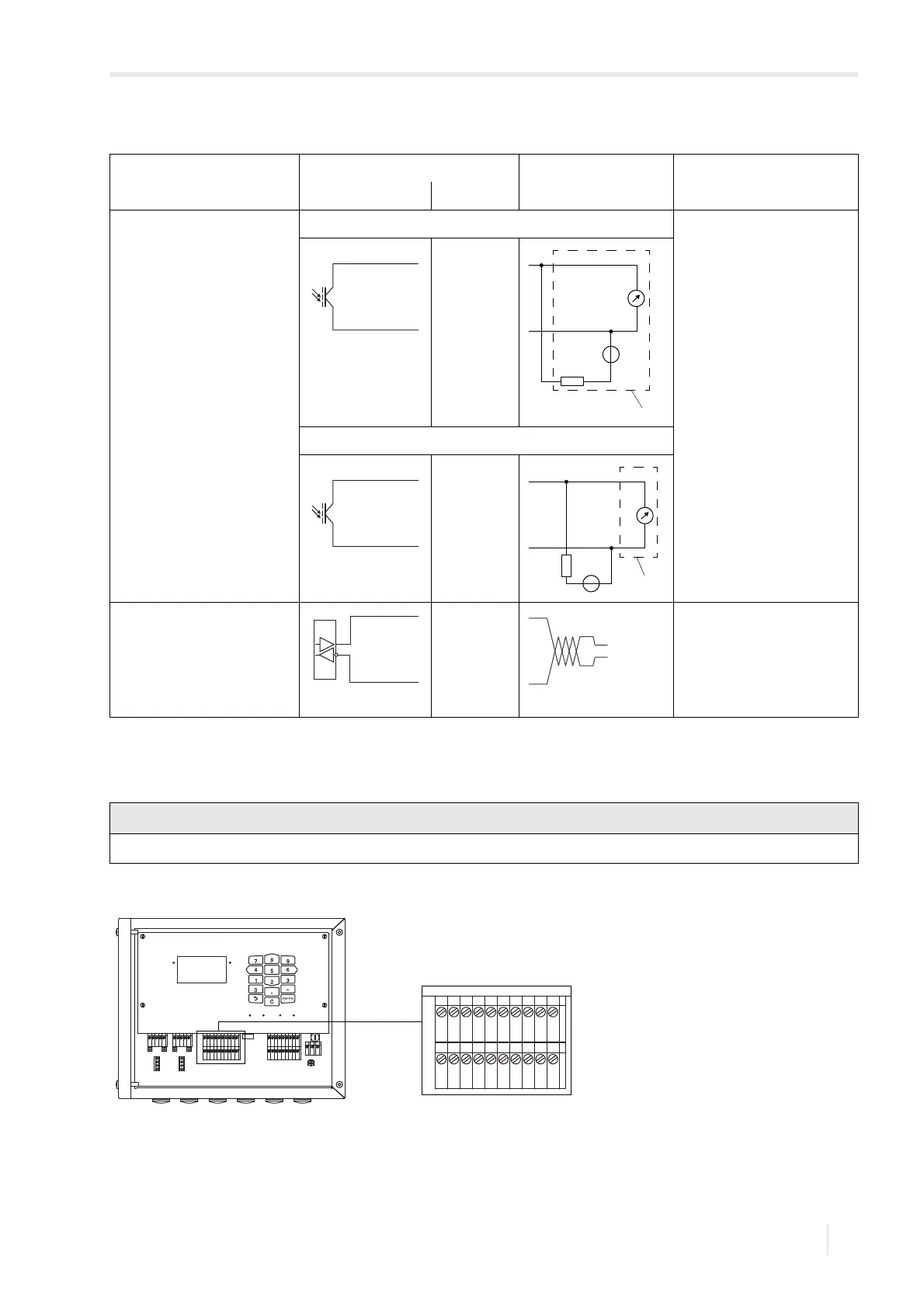
digital output
TF7-
*72***-******-******a-*****-**
a = M, P, Q
circuit 1 U
ext
=5…30V
I
c
< 100 mA
R
c
[kΩ]=U
ext
/I
c
[mA]
circuit 2
RS485 120 Ω
termination resistor
The max. permissible voltage between the inputs and against PE is 60 V DC (permanent).
Fig. 8.17: Connection of the inputs to the transmitter
Tab. 8.11: Output circuits
output transmitter external circuit explanation
internal circuit connection
The number, type and connections of the outputs depend on the order.
R
ext
is the sum of all ohmic resistances in the circuit (e.g., resistance of the conductors, resistance of the ammeter/voltmeter).
A
B
SNAP
DISP
DISP
MODEFAST
MUX
NEXT
Q
ON
Q+Q-
3x Q
OFF
LAN
USB
A+
B-
P1+
P2+
P3+
P4+
P5a
P6a
P7a
S
S
P1-
P2-
P3-
P4-
P5b
P6b
P7b
X2 X3
X_AV
KL11
KL12
KL7KL8
KL9KL10
KL4
X_AR X_BV X_BR
T1A
T1B
S1
T2A
T2B
T3A
T3B
S3
T4B
T4A
T1a
T1b
S1
T2a
T2b
T3a
T3b
S3
T4b
T4a
N(-)
PE
L(+)
AV
AVS
AGN
ARS
AR
BV
BVS
BGN
BRS
BR
T1A
T1B
S1
T2A
T2B
T3A
T3B
S3
T4B
T4A
T1a
T1b
S1
T2a
T2b
T3a
T3b
S3
T4b
T4a