EasyManuals Logo

Flexim PIOX S72 Series User Manual

Flexim PIOX S72 Series
225 pages
To Next Page IconTo Next Page
To Previous Page IconTo Previous Page
Page #84 background imageLoading...
Page #84 background image
8 Connection
8.3 Outputs PIOX S72*
2022-05-15, UMPIOX_S72xV1-9EN
84
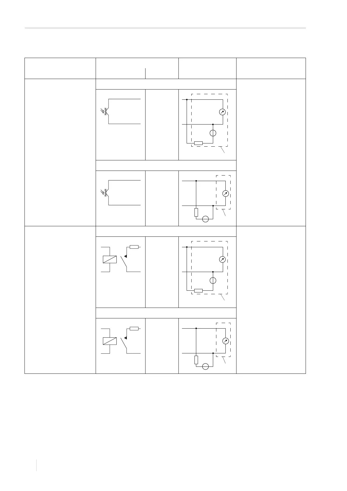
binary output (optorelay)
TF7-
*721**-******-******a-*****-**
a = U, V, D
circuit 1 U
ext
26 V
I
c
100 mA
R
c
[kΩ]=U
ext
/I
c
[mA]
circuit 2
binary output (Reed relay)
(*721)
circuit 1 U
max
= 48 V
I
max
= 100 mA
P1...P4: R
int
= 22 Ω
R
c
[kΩ] = U
ext
/I
max
[mA] - R
int
circuit 2
Tab. 8.11: Output circuits
output transmitter external circuit explanation
internal circuit connection
The number, type and connections of the outputs depend on the order.
R
ext
is the sum of all ohmic resistances in the circuit (e.g., resistance of the conductors, resistance of the ammeter/voltmeter).
Pxa
Pxb
R
c
V
U
ext
+
-
PLC
Pxa
Pxb
U
ext
R
c
V
+
PLC
-
R
int
Px+/Pxa
Px-/Pxb
R
c
V
U
ext
+
-
PLC
R
int
Px+/Pxa
Px-/Pxb
U
ext
R
c
V
+
PLC
-

Table of Contents

Questions and Answers:

Question and Answer IconNeed help?

Do you have a question about the Flexim PIOX S72 Series and is the answer not in the manual?

Flexim PIOX S72 Series Specifications

General IconGeneral
BrandFlexim
ModelPIOX S72 Series
CategoryMeasuring Instruments
LanguageEnglish

Related product manuals