8 Connection
PIOX S72* 8.1 Transducers
73
UMPIOX_S72xV1-9EN, 2022-05-15
8.1.3.2 Transducer cable with plastic jacket and stripped ends
• Remove the blind plug for the connection of the transducer cable.
• Open the cable gland of the transducer cable. The compression part remains in the cap nut.
• Push the transducer cable through the cap nut and the compression part.
• Prepare the transducer cable.
• Shorten the external shield and brush it back over the compression part.
• Screw the gasket ring side of the basic part into the junction box.
• Insert the transducer cable into the junction box.
• Fix the cable gland by screwing the cap nut onto the basic part.
• Connect the transducer cable to the terminals of the junction box.
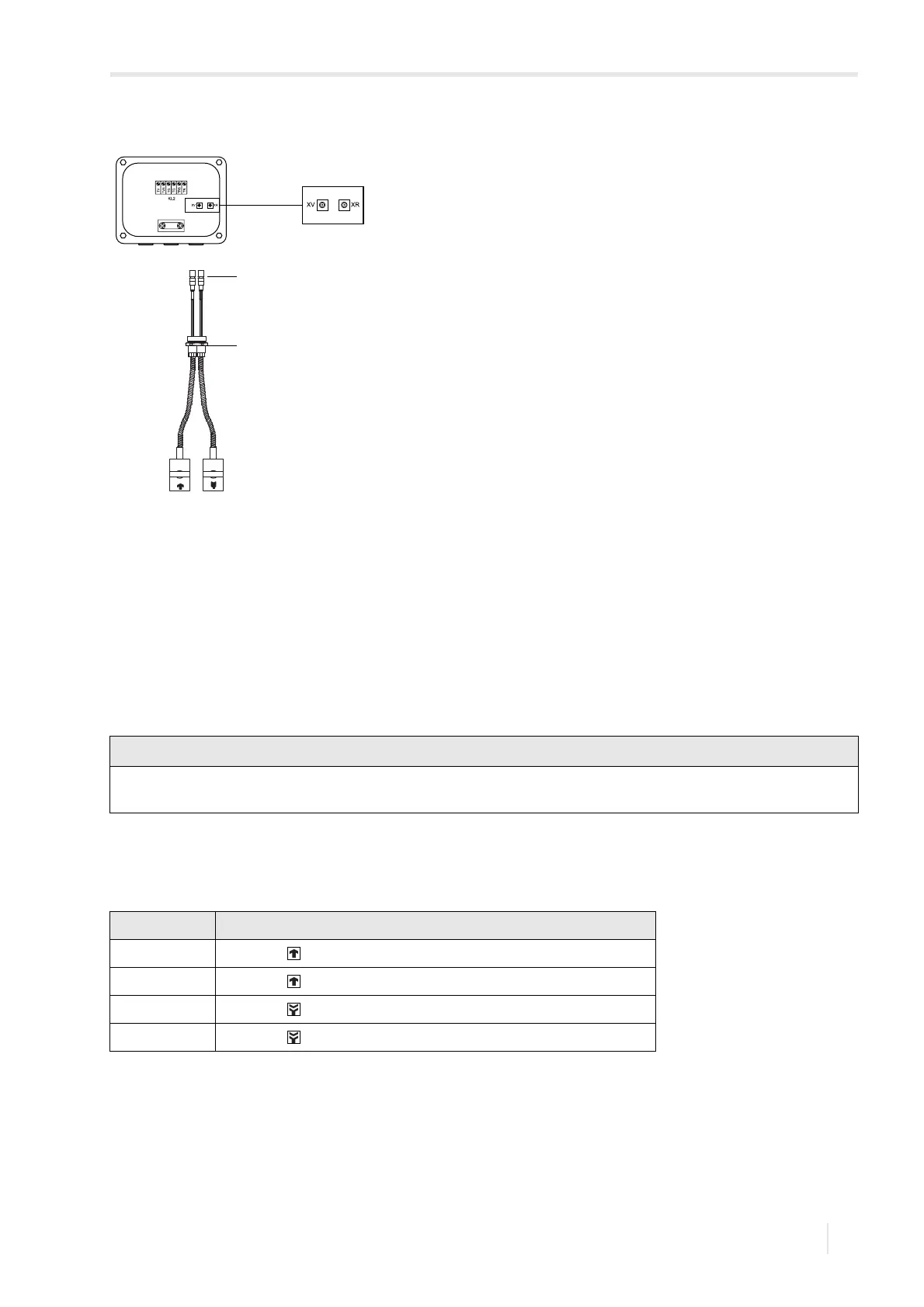
Fig. 8.6: Connection of the transducer cable with SMB connectors
1 – SMB connector
2 – cable gland
For good electromagnetic compatibility (EMC), it is important to ensure good electrical contact between the external
shield and the cap nut (and thus the housing).
Tab. 8.6: Terminal assignment
terminal connection
V transducer (core)
VS transducer (internal shield)
RS transducer (internal shield)
R transducer (core)