LEMO 1B, 6 pinsConnector type:
Pin numberTypeSignal name
1I/OUSB_D+
2I/OUSB_D-
3OUTUSB_POWER
4GNDGND
5OUTRS232_TX1
6INRS232_RX1
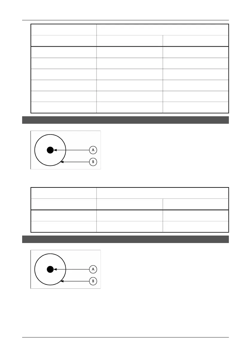
14.9.2 Power connector
10402503;1
Figure 14.2 Pin configuration for power connector (on camera – operator’s side). A: Center pin; B:
Chassis
2.5 mm DCConnector type:
Pin numberTypeSignal name
CENTER PINPOWER+12V
CHASSISPOWERGND
14.9.3 CVBS connector
10402503;1
Figure 14.3 Pin configuration for CVBS connector (on camera – operator’s side). A: Center pin; B:
Chassis
68 Publ. No. 1 557 536 Rev. a35 – ENGLISH (EN) – January 20, 2004
14.9 – Pin configurations
 Loading...