List of figures
1Figure 1.1 ...................................................................................................................................................................
3
Figure 2.1 FLIR Systems, Boston, USA, FLIR Systems, Danderyd, Sweden, and FLIR Systems,
Portland, USA. ......................................................................................................................................
4
Figure 2.2
LEFT: FLIR Systems’ Thermovision
®
Model 661. The photo is taken on May 30th,
1969 at the distribution plant near Beckomberga, in Stockholm, Sweden. The camera
weighed approx. 25 kg (55 lb), the oscilloscope 20 kg (44 lb), the tripod 15 kg (33
lb). The operator also needed a 220 VAC generator set, and a 10 L (2.6 US gallon) jar
with liquid nitrogen. To the left of the oscilloscope the Polaroid attachment (6 kg/13
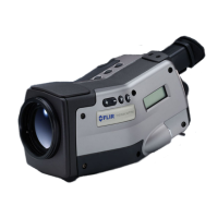
lb) can be seen. RIGHT: FLIR Systems’ ThermaCAM Model E2 from 2002 – weight:
0.7 kg (1.54 lb), including battery. ................................................................................................
4
Figure 2.3
LEFT: Development of system electronics; RIGHT: Testing of an FPA detector .........
5
Figure 2.4
LEFT: Diamond turning machine; RIGHT: Lens polishing ..................................................
5
Figure 2.5
LEFT: Testing of IR cameras in the climatic chamber; RIGHT: Robot for camera testing
and calibration .....................................................................................................................................
8Figure 4.1 System overview .................................................................................................................................
9Figure 5.1 How to connect system components, 1: Rear connectors ..................................................
9Figure 5.2 Explanations of callouts ....................................................................................................................
10Figure 5.3 How to connect system components, 1: Front connectors ................................................
10Figure 5.4 Explanations of callouts ....................................................................................................................
15Figure 6.1 Mounting an additional lens ..........................................................................................................
16Figure 6.2 Inserting the battery ..........................................................................................................................
17Figure 6.3 Removing the battery .......................................................................................................................
23Figure 7.1 Image transfer application ..............................................................................................................
24Figure 7.2 Image transfer ......................................................................................................................................
25Figure 7.3 Browse for images ..............................................................................................................................
26Figure 7.4 Options ...................................................................................................................................................
27Figure 7.5 RS-232 options .....................................................................................................................................
28Figure 7.6 Transfer application ...........................................................................................................................
29Figure 7.7 Starting the transfer application from Windows Start menu .............................................
32Figure 8.1 Camera parts, 1 ....................................................................................................................................
33Figure 8.2 Camera parts, 2 ....................................................................................................................................
35Figure 8.3 Camera parts, 3 ....................................................................................................................................
36Figure 8.4 Camera buttons – explanations ...................................................................................................
37Figure 8.5 Camera status LCD .............................................................................................................................
37Figure 8.6 Camera status LCD – explanations ..............................................................................................
39Figure 9.1 Explanation of measurement markers appearing in the result table ..............................
39
Figure 9.2 Status bar, showing atmospheric temperature, relative humidity, distance to target,
zoom factor, date & time, temperature range, emissivity, and reflected ambient
temperature. .........................................................................................................................................
39Figure 9.3 Temperature scale ..............................................................................................................................
40Figure 9.4 Status messages – a few examples .............................................................................................
40Figure 9.5 Critical camera information – a few examples ........................................................................
41Figure 9.6 File menu ...............................................................................................................................................
41
Figure 9.7
Open dialog box .................................................................................................................................
41
Figure 9.8
Directories dialog box ......................................................................................................................
42
Figure 9.9
Delete image dialog box .................................................................................................................
42
Figure 9.10
Analysis menu .....................................................................................................................................
43Figure 9.11 Temperature scale showing an isotherm set to above +62 °C ..........................................
43
Figure 9.12
Shortcut menu for Isotherm ..........................................................................................................
Publ. No. 1 557 536 Rev. a35 – ENGLISH (EN) – January 20, 2004 vii
 Loading...