Applications
Calibrating Insulation Resistance Testers 7
7-7
280V
RMS
MAX
280V
RMS
MAX
CAT I
1000V
CAT II
600V
RMS MAX
20V PK
30A
RMS
MAX
20V PK
LO
LO - SENSE
, HI ,
mA
V
1500V PK
MAX
50V PK
MAX
20V PK
20V PK
N
L
PE
L1 L2 L3HES
OUTPUT
Z
L
, Z
GND
,
RCD
HI
LO
HI
LO
METER
METER
5320A
MULTIFUNCTION ELECTRICAL TESTER CALIBR
V
A
COM
INPUT
Kikusui 7200
Fluke 5320A
ehq053.eps
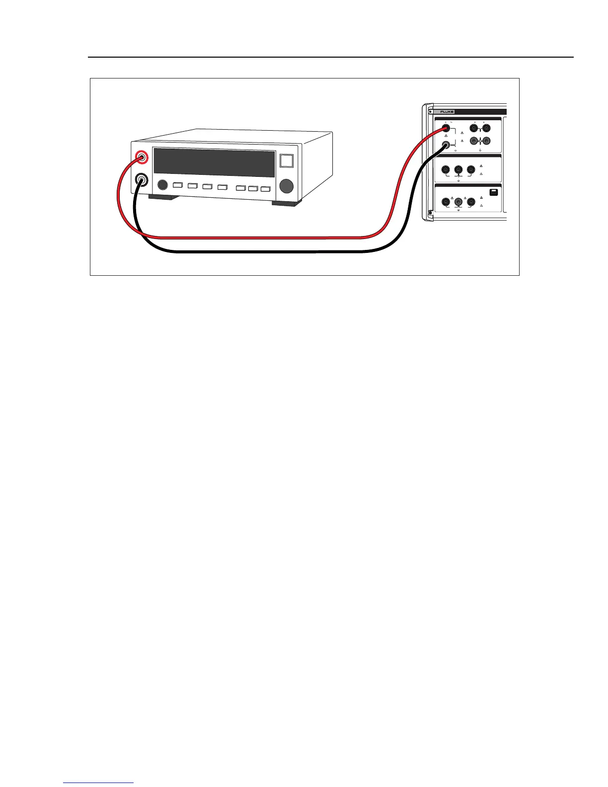
Figure 7-6. Calibrating Insulation Resistance of an Electrical Safety Analyzer
To perform an Insulation Resistance calibration:
1. Using Figures 7-4, 7-5, or 7-6, connect the UUT to the Calibrator’s HI Ω HI and LO
output terminals.
2. Press H.
3. If Short is displayed, press the Mode softkey. Then, using the cursor keys or rotary
knob, highlight Resistance and select it by pressing the Select softkey or pushing
in on the rotary knob.
4. Set the test voltage on the UUT.
W Caution
To avoid an overload condition, ensure the UUT test voltage is
below the Calibrator’s allowed voltage limit before adjusting the
resistance value.
5. If necessary, adjust the resistance value for the desired resistance.
6. Press O.
The test voltage generated by the UUT is measured by the Calibrator and displayed
in the parameters area of the display. For some insulation testers, a test button must
be pressed to start the measurement.
7. Activate the measurement on the UUT by pressing its start or test button.
8. Compare the UUT reading with the resistance value in the output area of the display.
9. Press S to disconnect the output terminals from the UUT.