5320A
Users Manual
7-28
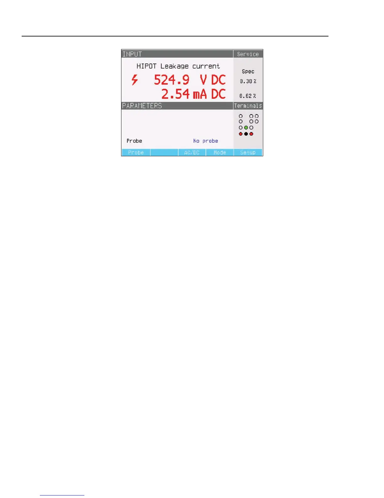
ehq64.bmp
Figure 7-27. Leakage Current Calibrator Display
3. The current type should be the same on the Calibrator and UUT. Set the Calibrator to
ac or dc depending on the signal type setup in the UUT.
4. Set the output voltage level on the UUT and turn the UUT output voltage on.
5. The Calibrator senses the output voltage and measures simulated leakage current
flowing through the Adapter.
6. To verify the leakage current performance on the UUT, compare the leakage current
readings on the UUT with those on the Calibrator.
Note
The Calibrator input resistance is 10 M
Ω
±
1 % connected in parallel with
the Adapter.
For making hipot leakage current calibrations using voltages higher than 1000 V, use the
10 kV HV divider as shown in Figure 7-28.