Home
Fluke
Control Unit
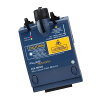
DTX-MFM2
Fluke DTX-MFM2 Technical Reference Handbook
4
of 1
of 1 rating
320 pages
Give review
Manual
Specs
To Next Page
To Next Page
To Previous Page
To Previous Page
Loading...
T
esting T
wisted Pair Thr
ough
a PoE Device
Running the AC Wire Map T
est as a Single T
est
4-7
4
Running the AC Wire Map Test as a
Single Test
To run the AC Wire Map test as a single test, enable the test
in SETUP, turn the rotary switch to
SINGLE TEST
; then select
Wire Map
.
122
124
Table of Contents
Default Chapter
3
Table of Contents
3
List of Figures
15
List of Tables
21
1 Getting Acquainted
23
Overview of Features
23
Registration
24
Additional Resources for Cable Testing Information
24
Contacting Fluke Networks
24
Unpacking
25
Dtx-1800
25
Dtx-1200
25
Dtx-Lt
26
DTX-MFM2 Multimode Fiber Modules (Optional)
26
DTX-GFM2 Multimode Fiber Modules (Optional)
26
DTX-SFM2 Singlemode Fiber Modules (Optional)
27
Safety Information
27
Basic Features
30
Physical Features
30
Changing the Language
36
Powering the Tester
36
About Link Interface Adapters and Modules
40
DTX Series Cableanalyzer Technical Reference Handbook
40
Verifying Operation
43
Checking the Hardware and Software Versions
44
The Main Autotest Screen
44
Setting User Preferences
46
Changing the Date, Time, and Date/Time Formats
46
Changing the Length Units
46
Changing the Numeric Format
46
Adjusting the Display Contrast
47
Setting the Power down Timer
47
Setting the Backlight Timer
47
Enabling or Disabling the Beeper
48
Overview of Memory Features
48
Inserting and Removing the Memory Card
48
Formatting the Memory Card (DTX-1800 and DTX-1200) or Internal Memory
48
Creating Folders
49
Setting the Storage Location (DTX-1800 and DTX-1200)
50
Options for Entering Cable Ids
50
Automatically Saving Results
51
Using the Talk Mode
52
About Linkware and Linkware Stats Software
52
2 Tutorials on Setup and Test Procedures
55
Preparing to Save Tests
55
Step 1: Checking the Memory Space Available
55
Step 2: Entering Job Information
55
Step 3: Setting the Storage Location (DTX-1800 and DTX-1200)
56
Step 4: Setting up a Job Folder
56
Step 5: Selecting a Cable ID Source
58
Certifying Twisted Pair Cabling
58
Required Equipment
58
Step 1: Checking the Battery Status and Verifying Operation with Twisted Pair Adapters
60
Step 2: Selecting a Test Limit, Cable Type, and Outlet Configuration
61
Step 3: Running the Autotest
62
Step 4: Viewing the Autotest Results
65
Step 5: Saving the Results
66
Certifying Fiber Cabling
66
Required Equipment
66
Step 1: Installing the Fiber Modules
68
Step 2: Checking the Battery Status and Verifying Operation with Fiber Modules
68
Step 3: Selecting a Fiber Type and Test Limit
69
Step 4: Configuring the Fiber Test
70
Step 5: Setting the Reference
70
Step 6: Running the Test
72
Step 7: Viewing the Results
73
Step 8: Saving the Results
73
Using the Auto Increment and Sequential Cable ID Features
74
Creating a List of Sequential Ids
75
About ANSI/TIA/EIA-606-A Cable Ids
77
3 Certifying Twisted Pair Cabling
79
Setting the Reference
79
Testing Twisted Pair Patch Cords
80
Twisted Pair Test Settings
81
DTX Series Cableanalyzer Technical Reference Handbook
82
Autotest on Twisted Pair Cabling
84
Twisted Pair Autotest Results
87
Automatic Diagnostics
89
PASS*/FAIL* Results
90
Wire Map
91
Resistance
93
Characteristic Impedance
94
Length
95
Propagation Delay and Delay Skew
96
Insertion Loss
97
NEXT (Near-End Crosstalk)
99
ACR (Attenuation to Crosstalk Ratio)
101
Return Loss
103
PSNEXT (Power Sum Near End Crosstalk) Test
105
PSACR (Power Sum Attenuation to Crosstalk Ratio) Test
105
ELFEXT (Equal Level Far-End Crosstalk) Test
106
PSELFEXT Test
109
Running Single Tests
109
Monitoring Impulse Noise
111
Using the Tone Generator
114
4 Testing Twisted Pair through a Poe Device
117
Enabling the AC Wire Map Test
117
Autotest through a Poe Device
117
AC Wire Map Results
120
Running the AC Wire Map Test as a Single Test
123
5 Certifying Coaxial Cabling
125
Setting the Reference
125
Coaxial Test Settings
126
Autotest on Coaxial Cabling
129
Coaxial Autotest Results
133
HDTDR Analyzer
134
Resistance
134
Impedance
134
Length
134
Propagation Delay
134
Insertion Loss
135
Running Single Tests
135
6 Diagnosing Copper Cabling Faults
137
Using the Automatic Diagnostics
137
Avoiding Tester-Induced Failures
137
Common Causes of Copper Cabling Failures
138
The HDTDX Analyzer
145
Running the HDTDX Analyzer
145
Recognizing Faults on HDTDX Plots
147
The HDTDR Analyzer
148
Running the HDTDR Analyzer
148
Recognizing Faults on HDTDR Plots
148
7 Certifying Fiber Optic Cabling
153
Overview of Features
153
Safety Information
154
Installing and Removing Fiber Modules
156
Installing the Connector Adapter
158
Verifying Operation
160
Essentials for Reliable Fiber Test Results
161
Cleaning Connectors and Adapters
161
About Setting the Reference
162
Testing Your Reference Test Cords
163
Using Mandrels for Testing Multimode Fiber
163
Fiber Test Settings
166
About Method B Connections
170
Autotest in Smart Remote Mode
170
Setting the Reference for Smart Remote Mode
172
Running the Autotest in Smart Remote Mode
174
Smart Remote Mode Autotest Results
176
Autotest in Loopback Mode
178
Setting the Reference in Loopback Mode
180
Running the Autotest in Loopback Mode
182
Loopback Mode Autotest Results
184
Autotest in Far End Source Mode
186
Setting the Reference in Far End Source Mode
188
Running the Autotest in Far End Source Mode
190
Far End Source Mode Autotest Results
192
Bi-Directional Testing
194
Bi-Directional Results for Smart Remote Mode
194
Bi-Directional Results for Loopback Mode
194
Finding Connections with Findfiber
196
Using Findfiber in Smart Remote Mode
196
Using Findfiber in Loopback Mode
201
Using the Power Meter
203
Running Single Tests
207
Using the Remote Tester with an Optifiber Tester
207
8 Locating Fibers and Faults with the Visual Fault Locator
209
Visual Fault Locator Applications
209
Using the Visual Fault Locator
210
9 Diagnosing Fiber Cabling Faults
213
Common Causes of Failures
213
Diagnosing Failures
214
10 Verifying Network Service
217
Overview of Features
217
Software Requirements
217
Installing and Removing the Network Module and Optional SFP Module
218
Verifying Network Connectivity
220
Network Connectivity Test Settings
220
Entering Ping Addresses
221
Running the Connectivity Test
222
Saving Connectivity Results
222
Pinging Network Devices
227
Monitoring Network Traffic
229
Blinking a Port Light
231
Identifying Links (Twisted Pair Only)
231
Diagnosing Low-Level Network Problems
233
DTX Series Cableanalyzer Technical Reference Handbook
234
11 Custom Test Settings
237
Creating a Custom Twisted Pair Cable Type
237
Creating a Custom Twisted Pair Test Limit
238
Creating a Custom Fiber Type
239
Creating a Custom Fiber Limit
240
Creating a Custom Outlet Configuration
241
Editing Custom Settings
242
Deleting Custom Settings
242
Changing the NVP
243
Setting the NVP to a Specified Value
243
Determining a Cable's Actual NVP
243
Resetting the NVP to the Default Value
244
Transferring Custom Settings between Testers
244
12 Memory Functions
245
Storage Locations and Capacities
245
Checking the Memory Status
245
Setting the Storage Location (DTX-1800, DTX-1200)
247
Automatically Saving Results
247
Working with Folders
248
Creating a New Folder
248
Changing Folders
248
Deleting Folders
249
Viewing and Managing Saved Results
250
Moving or Copying Results to a Memory Card (DTX-1800, DTX-1200)
251
Deleting Results
251
Renaming Results
252
Sorting Results
252
Formatting a Memory Card (DTX-1800, DTX-1200) or Internal Memory
253
Memory Card Care (DTX-1800, DTX-1200)
253
Uploading Results to a PC
254
13 Maintenance and Specifications
255
Maintenance
255
Reference Procedure for Link Interface Adapters
255
Factory Calibration
256
Updating the Tester's Software
256
Cleaning
259
Retraining the Battery Gauge
260
Replacing the Battery
260
Fiber Module Maintenance
261
Storage
261
If Something Seems Wrong
261
Options and Accessories
264
Specifications
269
Environmental and Regulatory Specifications
269
Service Calibration Period
270
Standard Link Interface Adapters
270
Cable Types Tested
270
Time for Autotest
270
Summary of Performance Specifications
271
Length
271
Propagation Delay
272
Delay Skew
272
DC Loop Resistance Test
272
Measurement Accuracy
276
HDTDX Analyzer Specifications for Cables <100 M (328 Ft)
281
HDTDR Analyzer Specifications for Cables <100 M (328 Ft)
281
Characteristic Impedance
281
Impulse Noise
281
DTX-COAX Coaxial Adapter Specifications
282
DTX-NSM Module Specifications
284
DTX-MFM2/SFM2/GFM2 Fiber Module Specifications
285
Visual Fault Locator
289
Tone Generator
289
Power
290
Electromagnetic Compatibility
290
Input Ratings
290
Certification and Compliance
290
CSA Standards
290
Safety
291
Regulatory Information
291
Laser Classification and Safety for DTX-MFM2, DTX-GFM2, and DTX-SFM2 Fiber Modules
291
Memory for Test Results
291
Serial Interfaces
292
Dimensions (Without Adapter or Module)
292
Weight (Without Adapter or Module)
292
Display
292
Loss Test Methods for Fiber Cabling
295
Introduction
295
Method A/A.2
296
Method B/A.1
298
Method C/A.3
300
Modified Method B
302
The Alternate Method
305
Index
309
Other manuals for Fluke DTX-MFM2
User Manual
74 pages
4
Based on 1 rating
Ask a question
Give review
Questions and Answers:
Need help?
Do you have a question about the Fluke DTX-MFM2 and is the answer not in the manual?
Ask a question
Fluke DTX-MFM2 Specifications
General
Brand
Fluke
Model
DTX-MFM2
Category
Control Unit
Language
English
Related product manuals
Fluke DTX-SFM2
74 pages
Fluke DTX-GFM2
74 pages
Fluke 80TK
4 pages
Fluke 177 Series
6 pages