Certifying Twisted Pair Cabling
Twisted Pair Autotest Results
3-19
3
Insertion Loss
Note
Insertion loss is also known as attenuation.
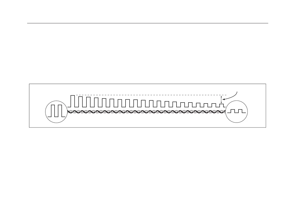
Insertion loss is the loss of signal strength over the cabling,
as shown in Figure 3-12. Insertion loss is caused by the
resistance of the copper wire and connecting hardware and
by leakage of electrical energy through the cable’s
insulation.
At higher frequencies, signals tend to travel only near the
surface of a conductor. This “skin effect”, along with the
cabling’s inductance and capacitance, cause insertion loss to
increase with frequency.
Figure 3-13 describes the insertion loss plot.
amd90f.eps
Figure 3-12. Insertion Loss is a Decrease in Signal Strength
Signal
source
Signal
output
Insertion loss

 Loading...