3.4 Programming Mode
3-38
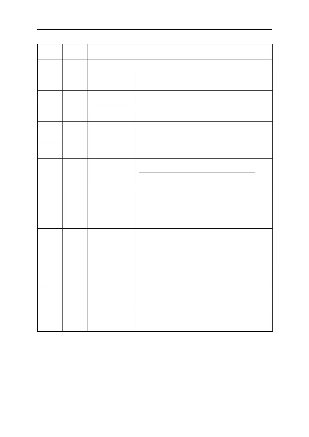
Table 3.4-14 “Alarm Information” display content
Output frequency before slip compensation when alarm
occurred
Output current when alarm occurred.
Unit: A (amperes)
Output voltage when alarm occurred
Unit: V (volts)
Calculated motor
output torque
Calculated motor output torque when alarm occurred
Frequency specified
by frequency
command
Frequency specified by frequency command when alarm
occurred
Displays the current rotation direction when alarm occurred.
f: forward, r: reverse, -----: stop
Running status in 4-digit hexadecimal format Refer to “
Displaying running status (3_07) and running status 2
(3_23)” in “3.4.3 Monitoring the running status “Drive
Monitoring: 3.ope””” on page 3-23 for details.
Displays the content of the cumulative power-ON time counter
of the inverter when alarm occurred.
Counter range: 0 to 65,535 hours
Display range: 0 to 65535
When the count exceeds 65,535, the counter will be reset to
“0” and start over again.
Displays the content of the motor startup counter (i.e., the
number of run commands issued) when alarm occurred.
Counter range: 0 to 65,535 times
Display range: 0 to 65535
When the count exceeds 65,535, the counter will be reset to
“0” and start over again.
Displays the DC link bus voltage of the inverter main circuit.
Unit: V (volts)
Temperature inside
the inverter
Displays the temperature of the inverter heat sink when alarm
occurred.
Unit: °C
Max. temperature of
heat sink
Displays the temperature of the inverter heat sink when alarm
occurred.
Unit: °C

 Loading...


