5.2 Function Code Tables
[ 6 ] A codes: Motor 2 Parameters (Motor 2 parameters)
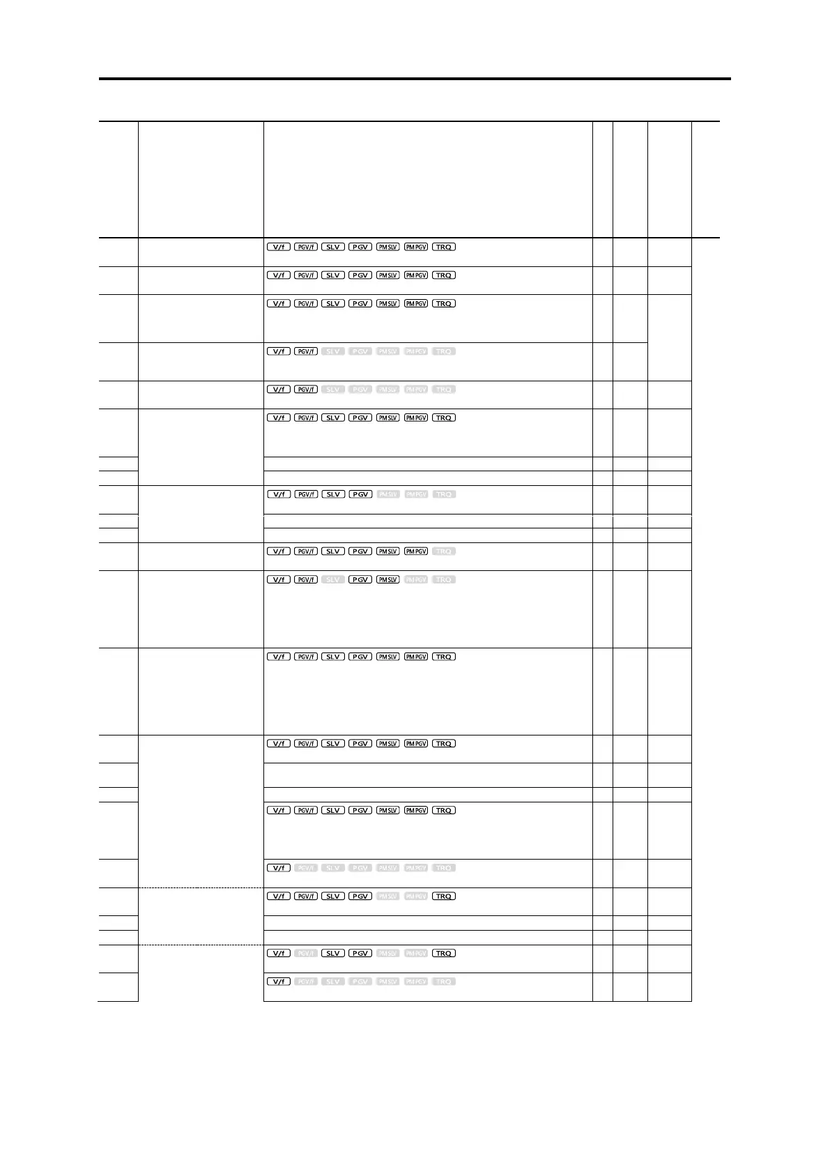
Control method and Data setting range
Maximum output frequency
2
Rated voltage at base
frequency 2
0: AVR disable (output voltage proportional to power voltage)
80 to 240 V: AVR operation (200 V series)
160 to 500 V: AVR operation (400 V series)
80 to 240 V: AVR operation (200 V series)
160 to 500 V: AVR operation (400 V series)
0.0 to 20.0 % (% value against base frequency voltage 2)
Electronic thermal overload
protection for motor 2
(Select motor
characteristics)
1: Enable (for a general-purpose motor with self-cooling fan)
2: Enable (for an inverter-driven motor with separately powered cooling
fan)
0.00 (disable), current value of 1 to 135 % of inverter rated current
DC braking 2
(starting frequency)
0 to 100 % (HHD specification), 0 to 80 % (HND specification)
0.00 (disable): 0.01 to 30.00 s
Load selection/
Auto torque boost/
Auto energy-saving
operation 2
0: Quadratic-torque load
1: Constant torque load
2: Auto torque boost
3: Auto energy-saving operation (quadratic-torque load)
4: Auto energy-saving operation (constant torque load)
5: Auto energy-saving operation with auto torque boost
Drive control selection 2
0: V/f control without slip compensation
1: Dynamic torque vector control
2: V/f control with slip compensation
3: V/f control with sensor
4: Dynamic torque vector control with sensor
5: Sensorless vector control
6: Vector control with sensor
0.01 to 1000 kW (when A39 = 0,2 to 5)
0.01 to 1000 HP (At P39 = 1)
0: Disable
1: Tune the motor while it is stopped
2: Rotation tuning
5: Stop tuning (%R1, %X only)
(Slip compensation gain for
driving)
(Slip compensation
response time)

 Loading...


