5.2 Function Code Tables
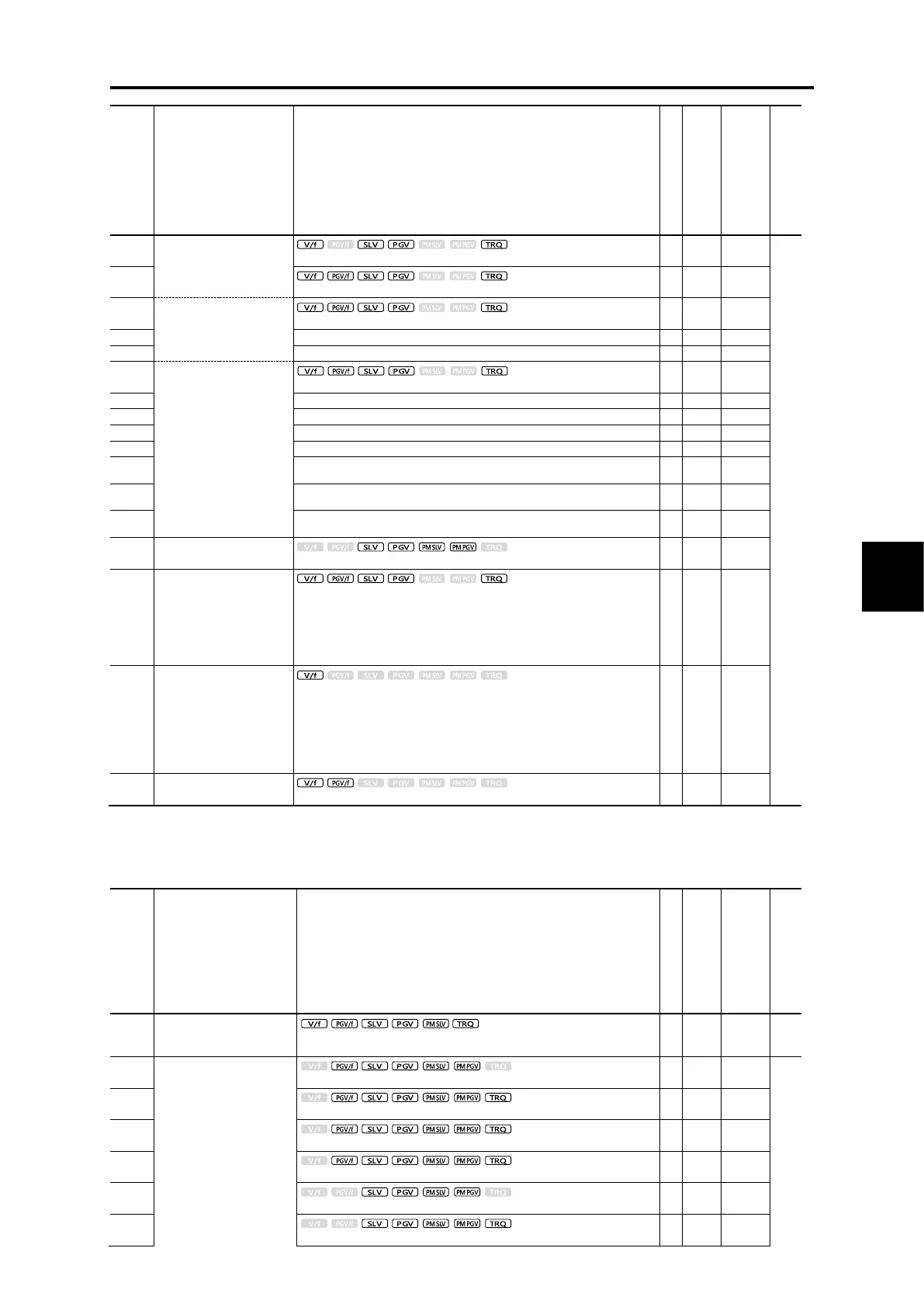
Control method and Data setting range
(Slip compensation gain for
braking)
(Magnetic saturation factor 1)
(Magnetic saturation factor 2)
(Magnetic saturation factor 3)
(Magnetic saturation factor 4)
(Magnetic saturation factor 5)
(Magnetic saturation
expansion coefficient a)
(Magnetic saturation
expansion coefficient b)
(Magnetic saturation
expansion coefficient c)
0: Motor characteristics 0 (Fuji standard IM, 8-series)
1: Motor characteristics 1 (HP rating IMs)
2: Motor characteristics 2 (Fuji dedicated motors for vector control)
3: Motor characteristics 0 (Refer to replacement material when using Fuji
standard IM, 6-series)
4: Other IMs
5: Motor characteristics 5 (Fuji premium efficiency motors)
Slip compensation 2
(Operating conditions
selection)
0: Enable during acceleration/deceleration, enable at base frequency or
higher
1: Disable during acceleration/deceleration, enable at base frequency or
higher
2: Enable during acceleration/deceleration, disable at base frequency or
higher
3: Disable during acceleration/deceleration, disable at base frequency or
higher
Output current fluctuation
damping gain for motor 2
*2: Factory defaults are depended on motor capacity. Refer to Table 5.2-1 Factory default settings by inverter capacity.
*3: The motor rated current is automatically set. Refer to Table 5.2-2 Motor constants (function code P03).
*6: Factory defaults are depended on motor capacity.
*10: 5.0 min for FRN0115G2S-2G/FRN0060G2-4G or lower inverters, 10.0 min for FRN0146G2S-2G/FRN0075G2-4G or higher inverters
Control method and Data setting range
Motor/parameter switching 2
(Operation selection)
0: Motor switching (Switching with motor 2)
1: Parameter switching (Switching with A code)
Speed control 2
(Speed command filter)
0.001 to 9.999 s, 999 (Cancel integral term)

 Loading...


