5.3 Description of Function Codes 5.3.5 H codes (High performance functions)
5.3.5 H codes (High performance functions)
The simulated operation function is used at the following times, and is performed without inverter output.
• When wishing to operate run commands and digital input terminals via a terminal block or communication in
order to check whether the inverter functions.
• When wishing to check digital output terminals and analog voltage/current, and pulse output, etc.
If performing vector control or feedback control such as V/f control with sensor, acceleration will not be possible
with the speed detection value at zero, meaning that it will not be possible to carry out tests of digital input/output
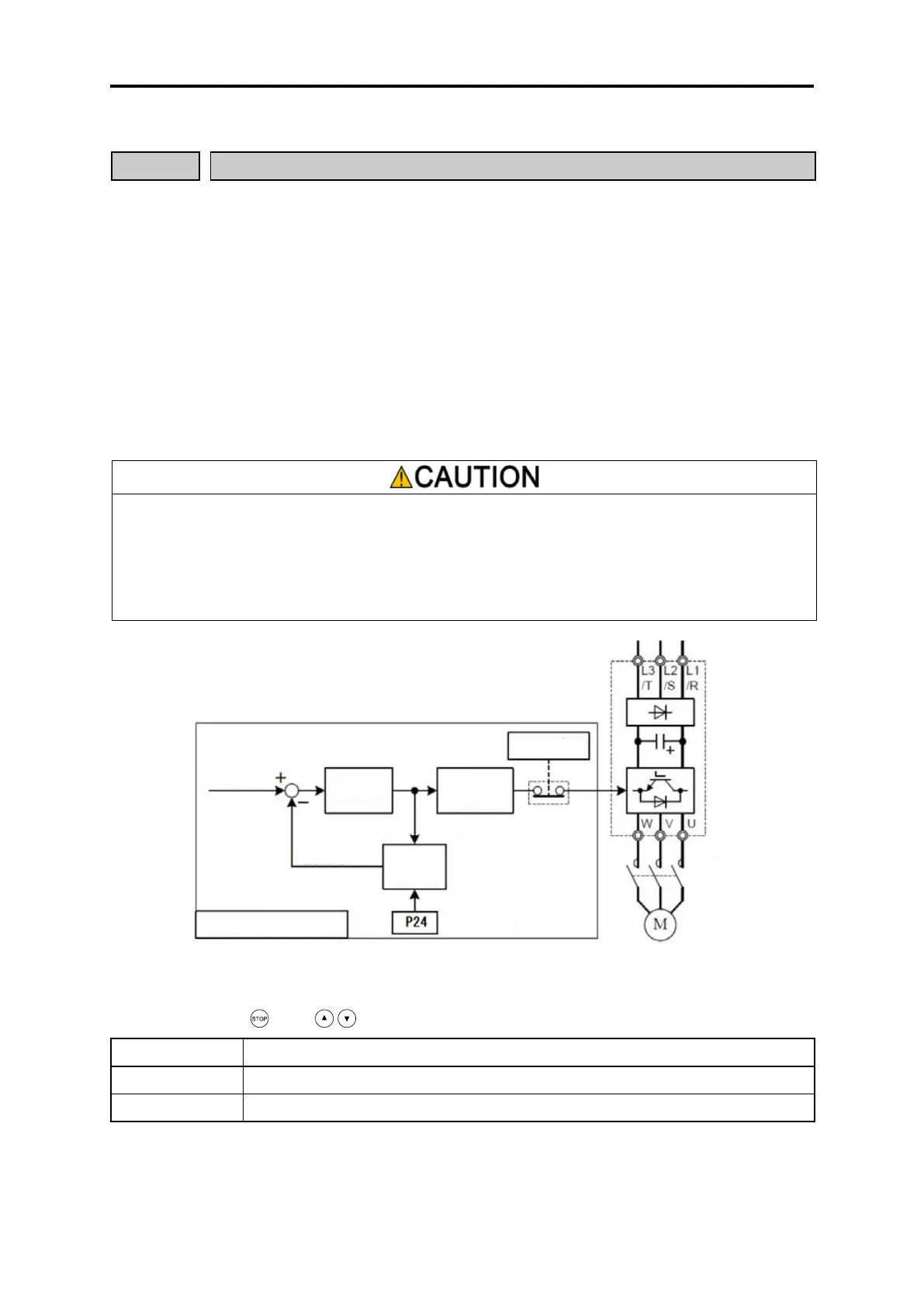
terminals such as speed arrival with the inverter alone. By selecting simulated operation with this function code, a
machine model is configured inside the inverter, and simulated feedback signals are generated, enabling
acceleration without connecting a motor. With simulated operation, however, no voltage is produced, and therefore
the current monitor value will always be zero even if a motor is connected. Simulated operation can be performed
even for other than control with sensor, and therefore this function can be used in cases where you do not want to
produce output voltage during testing.
There is no inverter output when performing simulated operation, but digital output signals such as “RDY”, “RUN”,
“RUN2”, and “AX” turn ON. If the machine brake is controlled with a RUN signal or frequency detection signal,
etc., ensure that the machine brake is not released unintentionally. Furthermore, voltage is not produced at the
inverter output side (U, V, W), but in the interests of safety, either isolate the output side, or shut off the output
side with a magnetic contactor.
Failure to observe this could result in an accident or injury.
With machine models simulated with the inverter, load inertia P24, A38, b38, and r38 are used. If 0.000 is set, it is
handled as 0.200.
Double key operation ( key + / keys) is required to change function code H00 data.
Normal operation (factory default)
Motor operating time, and startup count, etc. are not added during simulated operation. The operating time for
capacitors and cooling fans, etc. is added when the inverter power is ON.
Control area for simulated operation
Current control
Vector control

 Loading...


