CAUTION!
l To avoid temperature rise, replacing a hard disk should be finished within
5 minutes if the ETERNUS JX40 S2 is operating.
l Because of cooling, adherence to EMC (electromagnetic compatibility)
requirements and fire protection all unused bays must be filled up with
blank inserts.
6. Connect a power cord to each power supply of the storage modules.
It is recommended to connect each power cord (two per module) to a separate
AC circuit in order to ensure system availability in case of a power failure.
7. Turn on both PSU switches on the rear side of each storage module.
8. If the ETERNUS CS800 S6 was shut down prior to adding the new hardware, turn on the
server by pressing its power ON/OFF button now.
Otherwise, if the system was operable while the new disks were added, initiate a reboot
via the remote management pages (see "Reboot & Shutdown" on page 457).
9. Wait at least 15 minutes before starting any further actions. The integration of the added
disks takes place automatically, no further actions are required.
17.2 Storage Expansion - Scale
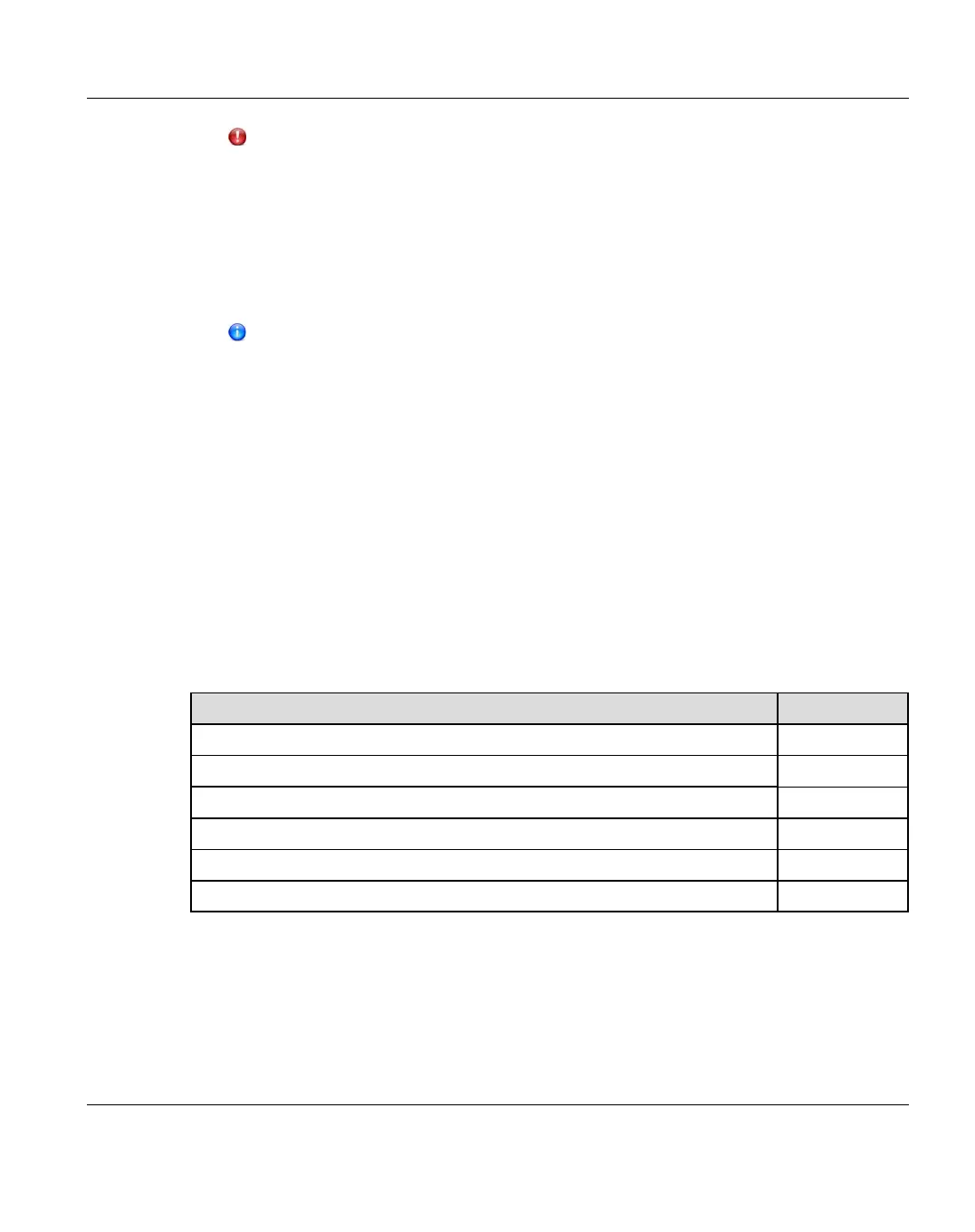
Table below shows the numbering schemes for the storage array(s). Figure below shows the
recommended mounting positions of the modules in the rack.
Storage Modules Denotation
DX100 S3 base CE
1 DX100 S3 expansion module on the DX100 S3 base DE-1
2 DX100 S3 expansion module on the DX100 S3 base DE-2
3 DX100 S3 expansion module on the DX100 S3 base DE-3
... ...
10th DX100 S3 expansion module on the DX100 S3 base DE-a
Table 29: Numbering of the Storage Modules for a Scale System
ETERNUS CS800 483
17 Storage Expansion
 Loading...


