7 Protection Parameter Settings
This cell sets the Green LED L5 – L8 for desired function.
4.
Gen Strt*
00
1 = assigned ; 0 = not assigned
This cell sets the RED LED L5 – L8 for desired function.
5.
Gen Strt*
0000
1 = assigned ; 0 = not assigned
This cell sets the input for AND Logic equation (A, B, C and D).
6.
Rem.Rst*
0000
1 = assigned ; 0 = not assigned
This cell sets the Opto I/P 1 – Opto I/P 6 for desired function.
* Note: The functions which can be assigned to Output Relay, LED Green, LED RED, AND Logic and Opto
I/P are listed in Chapter 8: Monitoring and Control.
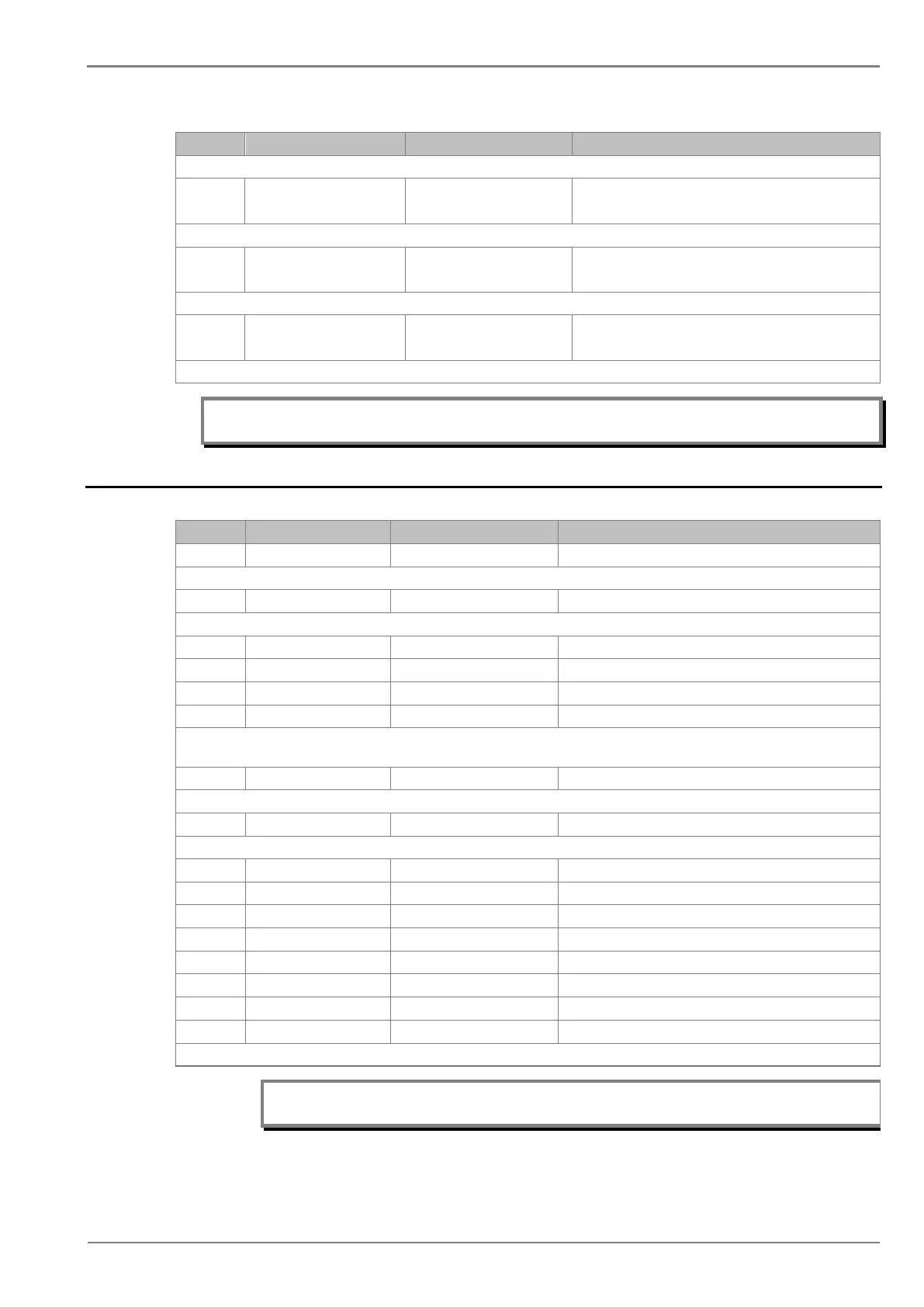
2.9 O/P RELAY CONFIG Settings
Sr. No Parameter Defaults setting Setting / Ranges
1. Password 0000 0000 to zzzz
This setting specifies to enter the set password
This setting specifies the reset mechanism (manual / hand reset or self reset ) for O/P relay contacts.
3. O/P-1 Open Time 0.50 S 0s to 1s step 0.01s
4. O/P-2 Open Time 0.50 S 0s to 1s step 0.01s
5. O/P-3 Open Time 0.50 S 0s to 1s step 0.01s
6. O/P-4 Open Time 0.50 S 0s to 1s step 0.01s
This setting specifies the time duration for which the output contacts holds its state after non availability of the command to the O/P
contact.
7. LED G HR/SR 00 1= HR / 0 = SR
This setting specifies the reset mechanism (manual/hand reset or self reset ) for Green LED.
This setting specifies the reset mechanism (manual/hand reset or self reset ) for RED LED.
9. ANDEQ A Op Time 1 S 1s to 3600s step 1s
10. ANDEQ A Rst Time 1 S 1s to 3600s step 1s
11. ANDEQ B Op Time 1 S 1s to 3600s step 1s
14. ANDEQ C Rst Time 1 S 1s to 3600s step 1s
15. ANDEQ D Op Time 1 S 1s to 3600s step 1s
16. ANDEQ D Rst Time 1 S 1s to 3600s step 1s
These settings specifies the operating / reset time delay allocated to the logic AND equation.
Note: In the P50 Agile Configurator, the above settings parameters from serial no 7 to 16
are available under “IO Mask”.
 Loading...


