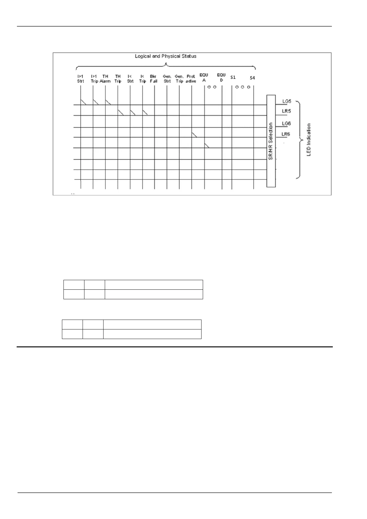
Figure 3: LEDs configuration logic
The functions that can be assigned to Green LED and Red LED are same to relay contact.
All Green LEDs and Red LEDs can be individually set as self-reset or latching
The selection of HR/SR type is made by changing bits value from 0 or 1 in O/P Contact
Configuration setting.
For Self-reset output contact, set bit 0
For Latch type (HR) output contact, set bit 1.
The bit position for Green LEDs is as shown in following table.
LG-6 LG-5
0 0 1 is HR type & 0 is SR type
The bit position for Red LEDs is as shown in following table.
LR-6 LR-5
0 0 1 is HR type & 0 is SR type
2.7 Logic Equations
The device supports 4 Logic AND equations which can be used to form Boolean functions using AND
operators. Any function available in the IO Mask can be assigned to any single equation. Maximum
numbers of signals that can be assigned to any equation depends on the number of functions
available in IO mask for assignment.
The Logic equations are identified as
AndLogicA, AndLogicB, AndLogicC and AndLogicD.
Any protection functions, Control Operation and opto I/Ps can be assigned to the AND logic equations
and result of equation can be time delayed and assigned to any output relays and LEDs. The relevant
settings are available under O/P Relay configuration menu.
The signals available for mapping to an equation are same as available for Relay contacts and LEDs.
 Loading...


