2.3.3.3 Rear Serial Port connection
The rear serial port is intended for use with a permanently wired connection to a remote SCADA
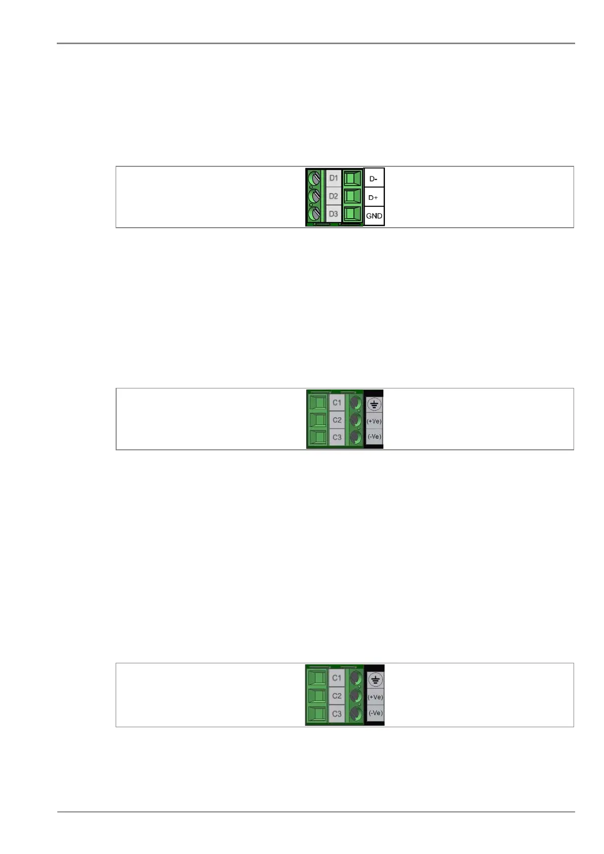
system. The physical connectivity is achieved using three terminals: D1, D2 terminals for signal
connection, and D3 terminal for connecting cable shield. The terminal block is located at the rear of
the relay as shown below.
Figure 8: Rear serial port terminal block
2.3.3.4 Power Supply Connections
These should be wired with 1.5 mm
2
PVC insulated multi-stranded copper wire terminated with M3 pin
terminals. The wire should have a minimum voltage rating of 300 V RMS.
When wiring auxiliary supply input of the relay, adequate care should be taken to wire as per polarity
marking on the Terminal sticker at the rear of the relay. The supply range is also mentioned on the
Terminal sticker and before energising, care should be taken to confirm that the auxiliary supply being
wired is within range.
Figure 8: Auxiliary supply terminals
2.3.3.5 Earth Connection
Every device must be connected to the cubicle earthing bar. Earthing terminal (C1) is provided on
back side of the relay. Ensure that the relay earthing is connected to the local earth bar. With several
relays present; make sure that the copper earth bar is properly installed for solidity connecting to the
earthing terminal of each relay equipment box.
Before energizing the equipment, it must be earthed using the protective conductor terminal, (if
provided) or the appropriate termination of the supply plug in the case of plug connected equipment.
The protective conductor (earth) connection must not be removed since the protection against electric
shock provided by the equipment would be lost. The recommended minimum protective conductor
(earth) wire size is 2.5 mm² or as per industries standard practice. The protective conductor (earth)
connection must be of low-inductance and as short as possible.
Figure 9: Earthing terminal on the rear side of the relay
 Loading...


