12 Maintenance and Troubleshooting
3 TROUBLESHOOTING
The relay continuously monitors the hardware and detects any hardware fault/error. In case of
hardware failure relay displays the corresponding error code on the LCD.
• The IED performs continuous periodic self-diagnostic procedure at every one minute for
checking of all errors excluding Setting Error.
• If the error is cleared during self-diagnostic procedure, corresponding error bit will be cleared.
• For Setting Error, ADC Error and FRAM1 Error, IED goes in OUT OF SERVICE mode
(Protection will be blocked). The OUT OF SERVICE LED on the front facia will continuously
blink at 1 sec interval and ON LED indication will turn from GREEN to RED.
The faults errors are stored in the ‘Main’t Rec Num= “and can be viewed from Maint Record
submenu. The Error code is stored in 16 bit integer.
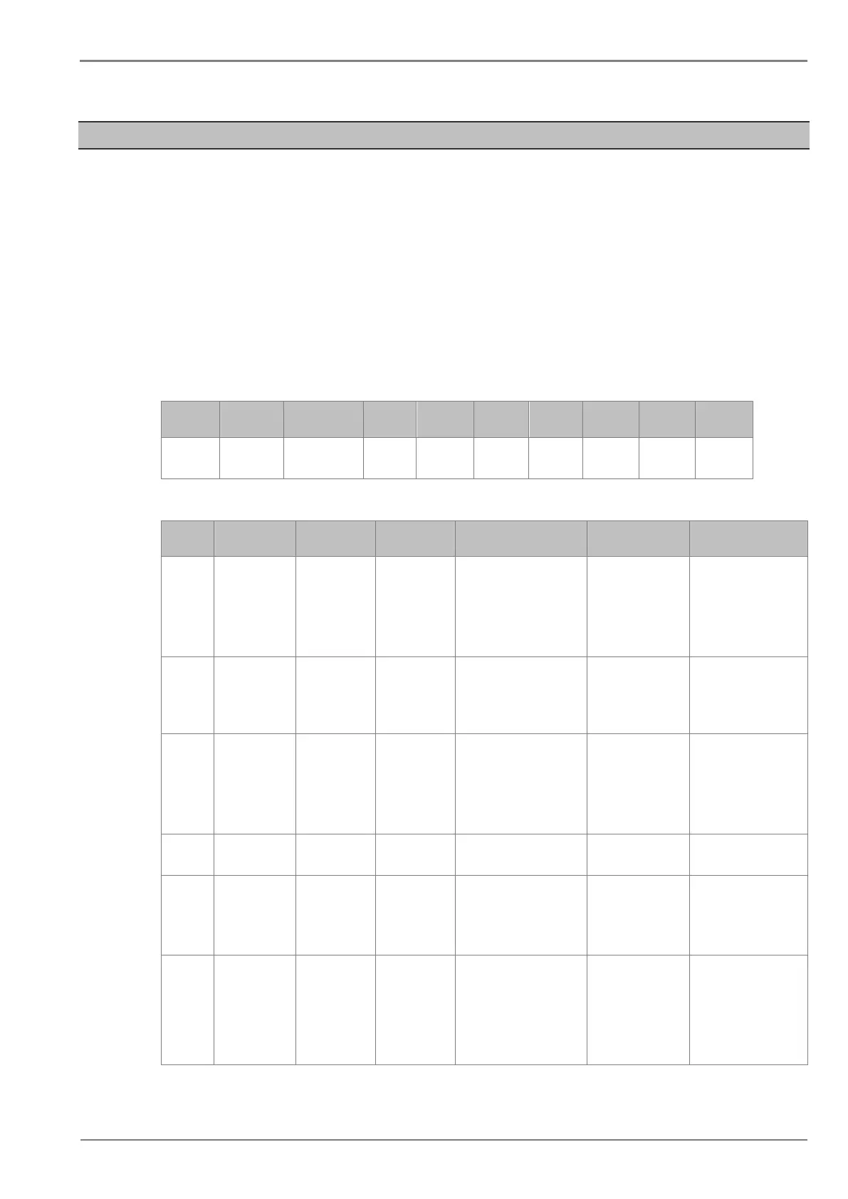
The bit definition applicable to P153 is shown as below:
Bit 12 -
Bit 11 Bit 10 Bit 6-9 Bit 5 Bit 4 Bit 3 Bit 2 Bit 1 Bit 0
Unused
Firmware
Incompatible
Unused
FRAM 1
Error
ADC
Error
Unused
RTC
Error
Unused
Setting
Error
The Error code descriptions are given below:
Sr. No
Error Code
Error Data
Description
Cause
Action taken
Proposed action
1 0001
0000 0000
0000 0001
SETTING
Error
1. Setting corrupted
2. Change of Setting
address in memory
and OUT OF
SERVICE LED
starts blinking.
(Protection is
blocked)
Go to
CONFIGURATION
menu, restore default
settings and then save
settings. Press (EDIT +
CLEAR).
2 0004
0000 0000
0000 0100
RTC
Error
1. I2C Bus Error
2. Damaged RTC
3. Battery backup not
functioning
ON LED turns Red
Set correct values for
Date & Time and press
(EDIT + CLEAR).
3 0010
0000 0000
0001 0000
ADC
Error
1. ADC device not
working.
2. SPI bus error
LED turns Red
and OUT OF
SERVICE LED
starts blinking.
(Protection is
blocked)
Press (EDIT + CLEAR)
4 0020
0010 0000
FRAM 1
Error
2. FRAM not working
ON LED turns Red Press (EDIT + CLEAR)
5
Incompatible
CommFirmware
0000 0100
0000 0000
Incompatible
Error
has communication
protocol not compatible to
the protocol option as per
relay model number.
ON LED turns Red
the cortec information
on the relay.
6
Incompatible
Firmware
0000 1000
0000 0000
Incompatible
Firmware
Error
is not compatible to the
hardware as per relay
model number. (e.g.
mismatch in CT selection/
DI Input threshold voltage
etc.)
ON LED turns Red
and OUT OF
SERVICE LED
starts blinking.
(Protection is
blocked)
the cortec information
on the relay.
 Loading...


