For details regarding the operating voltage and its threshold values, please refer to the Technical
Specification section of this manual.
2.5 Output Relays
The device supports 4 numbers of relay output. The use of these relay outputs depends on the
application. There are a number of settings associated with the relay outputs.
2.5.1 Output Relay Function Assignment
The relays have configurable logic outputs, which can be assigned to any available function. The logic
outputs are identified as RL1 to RL4. The logic outputs are available in configuration 2NO + 2C/O and
can be configured to change state on activation of the different functions available in the relay. A basic
output matrix is included in the P50 Agile configurator. Different functions can be assigned by using
P50 Configurator as well as relay user interface. On the user interface, the output relays can be
assigned to any function from I/O configuration menu. The function can be assigned to any input by
entering the values to them either 0 or 1 i.e. 0 = not assigned and 1 = assigned.
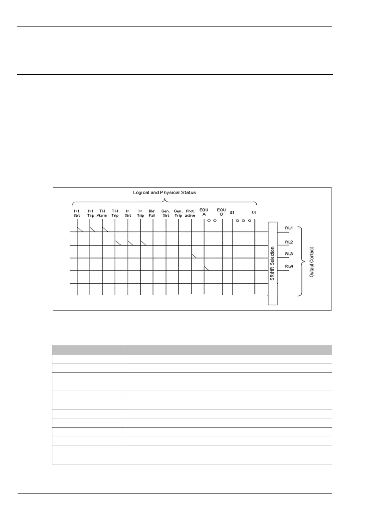
The following diagram explains the assignment process to relay either by UI or P50 Configuration.
Figure 1: Output contact configuration logic
The following functions can be assigned to the relay contacts.
Gen Strt General start
Strt L1 Start detected in phase A
Strt L2 Start detected in phase B
Strt L3 Start detected in phase C
Strt I>3 Start O/C stage 3
Strt I2>1 Start Neg seq. O/C stage 1
Strt I2>2 Start Neg seq. O/C stage 2
Strt I2>3 Start Neg seq. O/C stage 3
Start Measured E/F stage 1
StrtIN1>2 Start Measured E/F stage 2
 Loading...


