7 Protection Parameter Settings
2.10 DISTURBANCE RECORD Settings
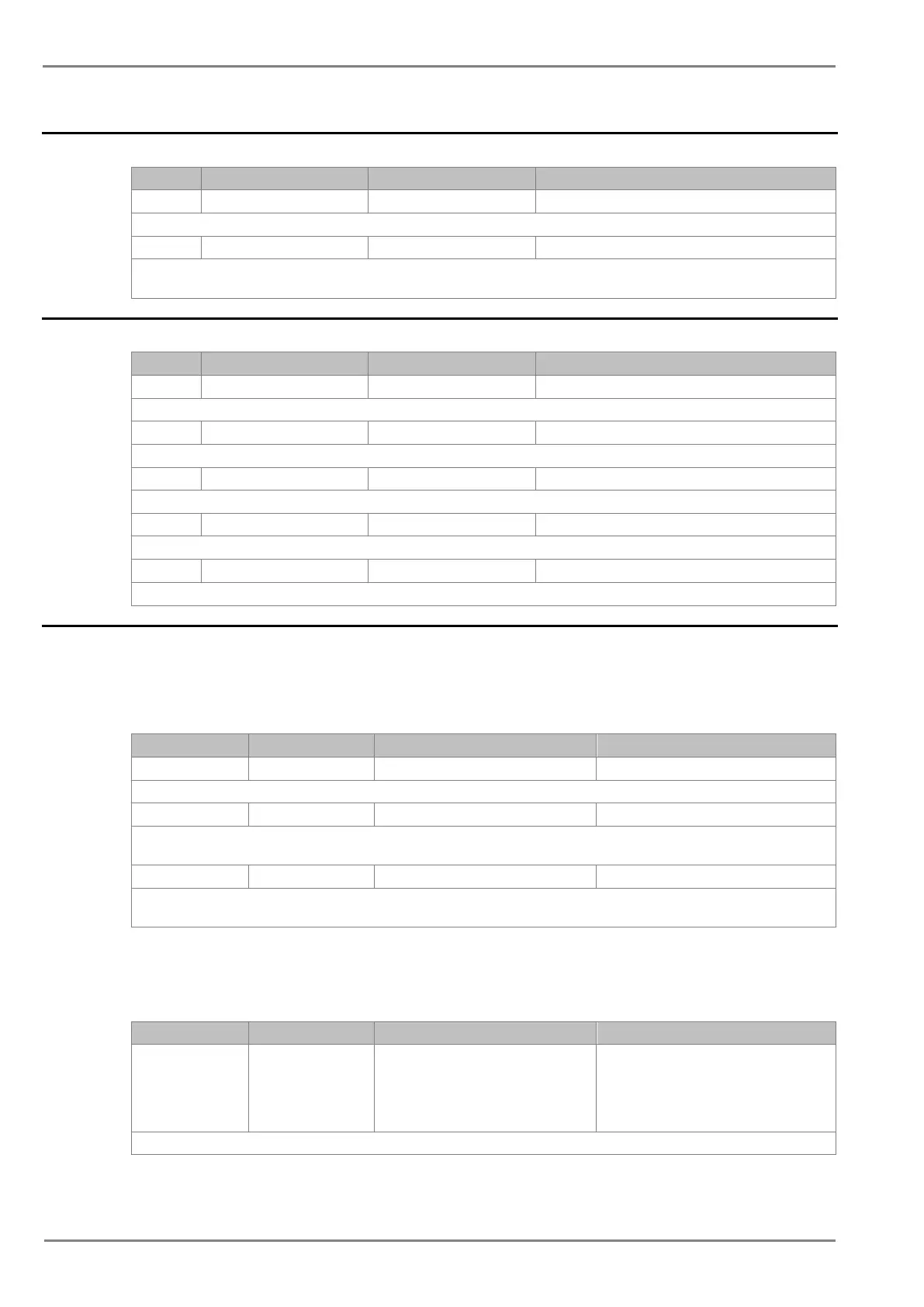
Sr. No Parameter Defaults setting Setting / Ranges
1. Password 0000 0000 to zzzz
This setting specifies to enter the set password
2. Trigger Position 50% 10% to 90% step 1%
This setting sets the trigger point as a percentage of the duration. For example, the default setting, which is set to 50% (of 1.0s) gives 0.5s
prefault and 0.5s post fault recording times.
2.11 COMMISSION TEST Settings
This setting specifies to enter the set password
2. Test Mode Disabled Disabled, Test Mode, Contacts Blocked
This setting allows secondary injection testing to be performed on the relay itself.
3. Test Pattern 000000 0 = not operated , 1 = operated
This setting is used to select the output relay contacts that will be tested when the Contact Test cell is set to Apply Test.
No Operation, Apply Test, Remove Test
This setting is used to test the relay output contact operation.
5. Test LEDs No Operation No Operation / Apply Test
This setting is used to test the 2 no’s programmable LED’s.
2.12 GROUP Settings
The following settings are common to GROUP 1 and 2.
2.12.1 SYSTEM CONFIG SETTINGS
This setting is used to enable or disable the 2nd Harmonic blocking of the overcurrent protection.
2. 2ndHarm Thresh 20% 5% to 70% step 1%
This setting is used to specify the 2nd Harm Threshold value. If the level of 2nd harmonic/fundamental in any phase current or neutral
current exceeds the setting, the overcurrent protection will be blocked as selected.
3. I>lift 2H 10.00*In 4 to 32*In step 0.01*In
The 2nd harmonic blocking is applied only when the fundamental current is above 2nd Harm Thresh and below I> lift setting. The reset
levels are 95% of these thresholds.
2.12.2 OVERCURRENT Settings
2.12.2.1 I>1 Function
1. I>1 Function IEC S Inverse
Disabled / DT / IEC S Inverse / S Inverse
(1.3Sec) / IEC V Inverse / IEC E Inverse / UK
LT Inve
rse / IEEE M Inverse / IEEE V Inverse
/ IEEE E Inverse / US Inverse / US ST
Inverse
This setting determines the tripping characteristic for the first stage overcurrent element.
 Loading...


