13 Technical Specifications
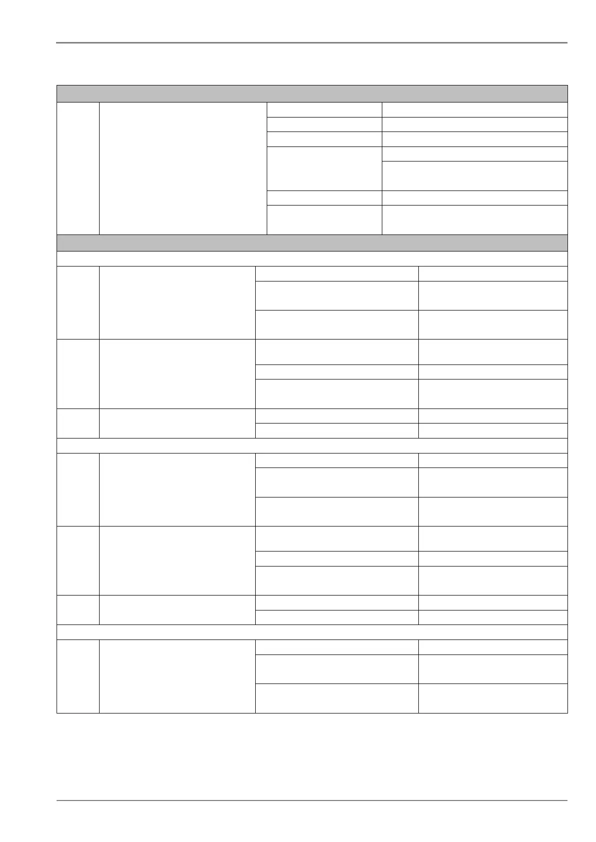
Output Contact
I.
Non Latching contact Continuous Continuous 5A/250 V AC
Short time withstand capacity
Breaking capacity AC- 1250 VA max. 5A or 250 V (PF= 0.4)
DC- 100 W resistive max. 5A or 300 V
50 W Inductive (L/R =45 ms) max. 5A or 300 V
Minimum no. of operations 10,000 operations loaded condition
100,000 operations unloaded condition
Accuracy of protection function
Overcurrent
I.
Operating value Pick-up Setting +10% / - 5%
Minimum trip level (IDMT) Setting ± 5% (for setting >=0.2In)
Setting ± 15% (for setting <0.2In)
Drop –off 0.95 x Setting ± 5% (for setting >=0.2In)
0.90 x Setting ± 15% (for setting <0.2In)
II.
Operating time IDMT characteristic shape
As per clause 5.2 of IEC60255-
50 ms whichever is greater
DT operation ± 5% or 55 ms whichever is greater**
** Reference condition Currents applied at 2x pick-up level or
higher
III.
Reset time DT Set delay ±10%
IDMT (only for IEEE & US curves) Calculated time ±10%
Earth Fault 1 (Measured)-Standard CT / SEF CT
I.
Operating value Pick-up Setting +10% / - 5%
Minimum trip level (IDMT)
Setting ± 5% (for setting >=0.2In)
Setting ± 15% (for setting <0.2In)
Drop –off 0.95 x Setting ± 5% (for setting >=0.2In)
0.90 x Setting ± 15% (for setting <0.2In)
II.
Operating time IDMT characteristic shape As per clause 5.2 of IEC60255-
50 ms whichever is greater
DT operation ± 5% or 55 ms whichever is greater**
** Reference condition Currents applied at 2x pick-up level or
higher
III.
Reset time DT Set delay ±10%
IDMT (only for IEEE & US curves) Calculated time ±10%
I.
Minimum trip level (IDMT)
Setting ± 5% (for setting >=0.2In)
Setting ± 15% (for setting <0.2In)
0.95 x Setting ± 5% (for setting >=0.2In)
0.90 x Setting ± 15% (for setting <0.2In)
 Loading...


