AquaTrans™ AT600 User’s Manual 27
Chapter 3. Wiring the AT600 Electronics
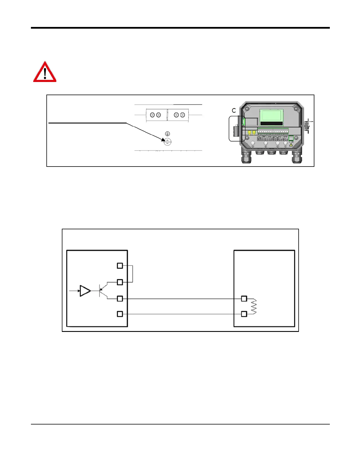
3.4 Wiring the System Ground
Figure 26: System Grounding Screw
3.5 Wiring the Analog Output for HART Communication
The standard configuration of the Model AT600 flow meter includes one isolated 0/4-20mA analog output.
Connections to this output may be made with standard twisted-pair wiring. The current loop impedance for
this circuit must not exceed 600 ohms.
Figure 27: Analog Output/HART Communication Wiring
WARNING! The AT600 must always be connected to a proper earth ground, using the system
grounding screw shown in Figure 26 below.
DETAIL C
SYSTEM GROUNDING SCREW
Model AT600
(Int. Pwr. Sup.)
HART Master/
Ampere Meter
Volts +
(Common)
Volts -
600 ohms)
(maximum
Load
PIN: 1
PIN: 0

 Loading...


