AquaTrans™ AT600 User’s Manual 17
Chapter 2. Clamp-On Fixture and Transducer Installation
2.1.3 Transducer Spacing = 0 to 250 mm or 0 to 320 mm, Traverses = 1, Fixtures = 2
For a one traverse installation with a calculated transducer spacing of 0 to 250 mm for a 2 MHz transducer or
0 to 320 mm for a 1 MHz or 0.5 MHz transducer, two clamp-on fixtures are installed on opposite sides of the
pipe. To install this configuration, complete the following steps:
1. Mark a straight line parallel to the pipe centerline on the top of the pipe (i.e., the 12 o’clock position).
2. Use a band tape to measure the circumference of the pipe. Then, mark two additional lines on the
pipe parallel to the first line. Locate these lines 1/4 of the way around the pipe in each direction from
the original line (i.e., at the 3 o-clock and 9 o’clock positions).
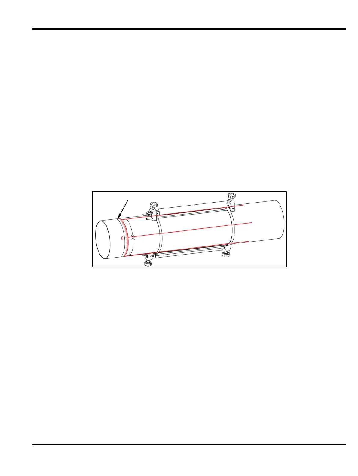
3. Install two mounting straps on the pipe about 12 in. (30 cm) apart (see Figure 19 below).
4. Hold one clamp-on fixture, with two transducers and one cable, on the pipe along one of the lines
marked in step 2. Then, move the two straps onto the ends of this fixture.
5. Hold the remaining (empty) clamp-on fixture on the opposite side of the pipe from the first fixture.
Then, move the two straps onto the ends of this clamp-on fixture.
6. Align the two fixtures to be equal distances from the band tape. Tighten both straps securely.
Figure 19: 1 Traverse Installation with 2 Fixtures
+
1
/
4
c
i
r
c
u
m
f
e
r
e
n
c
e
-
1
/
4
c
i
r
c
u
m
f
e
r
e
n
c
e
Band Tape

 Loading...


