1
2 3 4 5
6
1 0 1 2 1 3
1 4 1 5 1 6 1 7 1 8 1 9 2 0 2 1 2 2
1 6 . 5 V A C
+ 1 2 V
A B U S B
O U T 2
G N D
M I C
G N D
Z O N E 1 Z O N E 3
Z O N E 2
G N D
Z O N E 4
Z O N E 6
G N D
Z O N E 5
G N D
2 3
2 4 2 5
Z O N E 7
2 W S M K
Z O N E 8
G R N
+
-
+
-
7
8
9
S P E A K E R
O U T 1
2 6
2 7 2 8
7
8
B R N
G R Y
R E D
6
1
2 3 4 5
1
+ 1 2 V
2
A
3
B
4
G N D
5
G N D
6
S P K 1
7
S P K 2
8
A U D 1
9
A U D 2
1 0
G N D
1 1
T I P 1
1 2
T I P 2
1 3
R I N G
2
1 4
R I N G
1
3 4 5
6
+ 1 2 V
A
B
G N D B U S
2 6 2 7 2 8
2 5
7
8
1 2 3 4 5 6 7 8 9 1 0 1 1 1 2 1 3 1 4 1 5 1 6
Z O N E C O M M O N
Z O N E 1
Z O N E 2
Z O N E 3
Z O N E 4
Z O N E 5
Z O N E C O M M O N
Z O N E C O M M O N
Z O N E 6
Z O N E 7
Z O N E C O M M O N
Z O N E 8
N O 1
N C 1
C O M 1
Z O N E 1
N O 2
N C 2
C O M 2
N O 3
N C 3
C O M 3
N O 4
N C 4
C O M 4
Z O N E C O M
1 2 3 4 5 6 7 8 9 1 0 1 1 1 2 1 3 1 4 1 5 1 6 1 7 1 8
1 1
+ 1 2 V
T E L C O
H O U S E
S P E A K E R
3 4 5 6
+ 1 2 V
A
B
G N D B U S
3 4 5
6
+ 1 2 V
A
B
G N D B U S
3 4 5
6
+ 1 2 V
A
B
G N D B U S
F U R T H E R
+ 1 2 V
A
B
B U S
G N D
7 8
S P E A K E R
3 4
+ 1 2 V
G N D
1 2
M I C
G R N
B R N G R Y R E D
L P
-
+
L N
1 1
+ 1 2 V
+
_
Class II
16.5 VAC
40 VA
NOTE 1: Class II Power
Transformer
(600-1023 or 600-1024)
NOTE 2:
SuperBus 2000 2x16
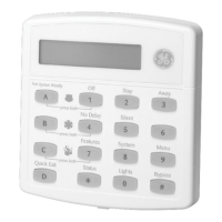
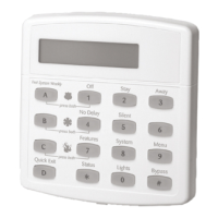
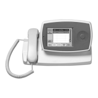
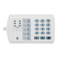
LCD Alphanumeric Touchpad
(60-746-01) shown.
Others similar.
NOTE 3:
8-Ohm, 15-watt
Speaker (13-060)
NOTES 4 & 9: Piezo Dynamic
Exterior Siren (13-950)
Red
Black
NOTES 4 & 9:
Hardwire
Interior Siren
(13-949)
GND
#1
NOTE 5:
Normally
Open (N/O)
Contacts in
Parallel
NOTE 5:
Normally
Closed (N/C)
Contacts
in Series
NOTE 5:
Normally
Closed (N/C)
Contacts
in Series
2k-Ohm EOL Resistor
(49-454)
2k-Ohm EOL
Resistor (49-454)
(Locate at last device)
NOTE 5:
PIR Motion
Sensor (13-082)
NOTES 3 & 8: Interrogator 200
Audio Verification Module (60-677)
NOTE 3: Hardwire Interior Speaker (60-528)
To Pa n el Te r min a ls 7 & 8
or
SuperBus 2000 Phone
Interface/Voice Module
Terminals 6 & 7
Not
Used
Other SuperBus 2000 Module Connections
To
To
Thermostat
Furnace
NOTE 10:
SuperBus
2000 Energy
Saver Module
(60-620-01)
NOTE 12:
SuperBus
2000 8Z Input
Module
(60-774)
NOTE 11:
SuperBus
2000 4-Relay
Output Module
(60-770)
NOTES 3 & 7: SuperBus 2000 Phone Interface/Voice Module (60-777-01)
(Partition 1
Voice Module
Only)
NOTE 13:
GRN
BRN
RED
GRY
RED
GRN
GRY
BRN
RING
(-)
TIP
(+)
RED
GRN
BLK
WHT
or
YEL
BRN
GRY
RED
GRN
RED
GRN
TO
PHONE
JACKS
TELCO
Protector
Block
Separate wire
cables
NOTE 7:
RJ-31X
(CA-38A)
Phone
Jack
DB-8 Cord
NOTE 7:
RJ-31X CA-38A)
Phone Jack
NOTE 6:
2-Wire
Smoke
Detectors
(Locate at last device)
Backup Battery
Panel Earth Ground
Connection
Pipe
WWW.DIYALARMFORUM.COM
 Loading...
