Concord 4 Series Systems
23
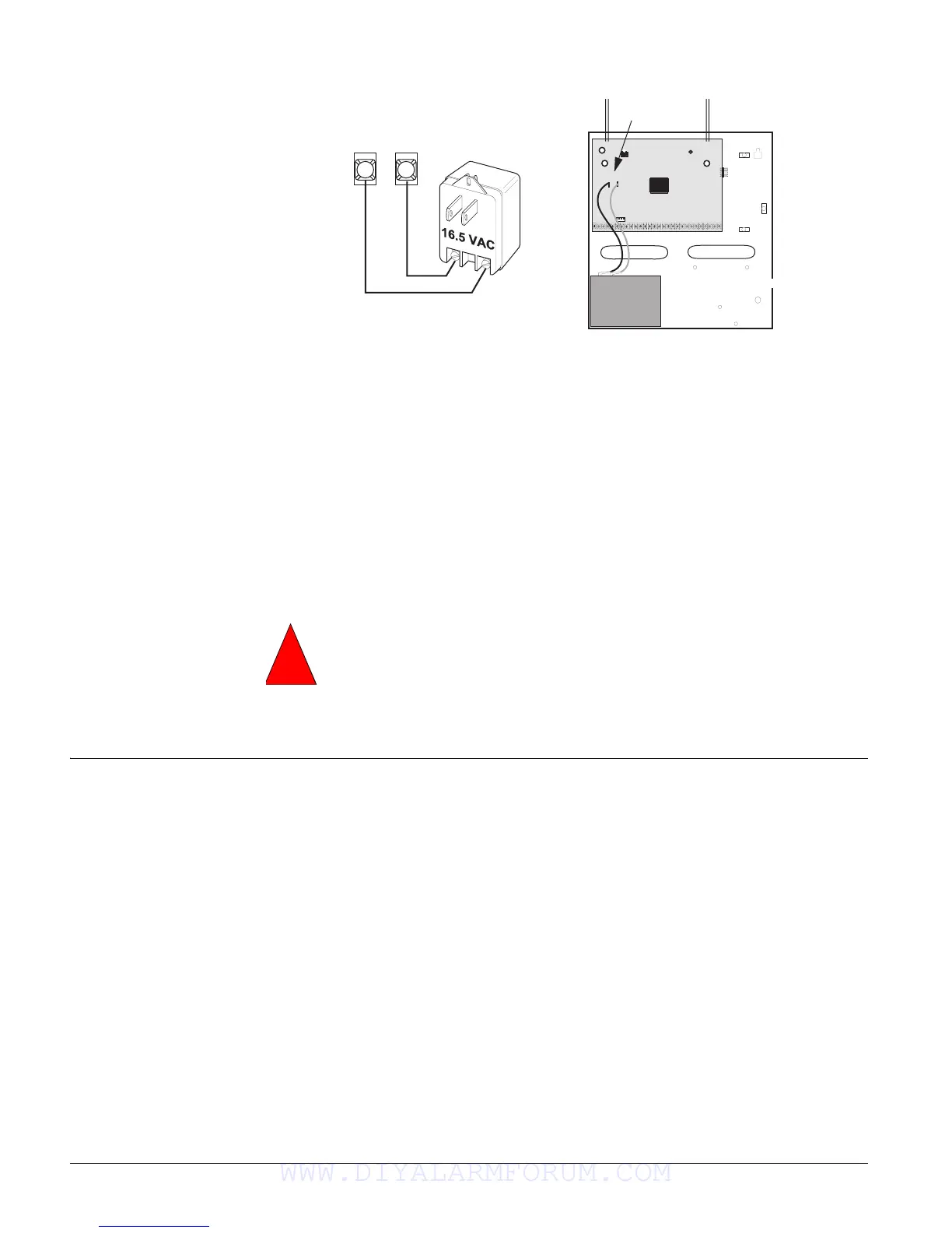
Figure 27. Connecting Panel Power Transformer and Backup Battery
Powering Up the Panel
After connecting and wiring all devices to the panel, you are ready to apply AC and backup bat-
tery power to the panel.
To power up the panel (see Figure 27):
1. Connect the red and black battery leads (included with panel) to the lugs on the panel.
2. Connect the other ends of the battery leads to the battery terminals.
3. Plug the transformer into an outlet that is not controlled by a switch.
Alphanumeric touchpads display
************, then SCANNING BUS DEVICES, and finally a
date and time display.
Note
If alphanumeric touchpads
don’t display anything,
immediately unplug the
transformer and disconnect
the backup battery. Refer to
the “Troubleshooting” sec-
tion.
4. To permanently mount the transformer, unplug it and remove the existing screw securing the
AC outlet cover.
Hold the outlet cover in place and plug the transformer into the lower receptacle.
5. Use the screw supplied with the transformer to secure the transformer to the outlet cover.
Programming
the Panel
For on-site system programming, an alphanumeric touchpad is required.
Entering Program Mode
Entering program mode is done using an installer/dealer code (default = 4321). The system can
be put into program mode only when all partitions are disarmed.
Note
If the system is powered up
after the programming
touchpad is connected or if a
bus command scan is exe-
cuted, the programming
touchpad will be “learned”
into the system and must
later be manually deleted.
To enter program mode:
1. Make sure the system is disarmed in all partitions.
2. Press 8 + 4321 + 0 + 0. The display shows
SYSTEM PROGRAMMING.
To enter programming mode using a programming touchpad:
1. Connect the red, black, green, and white wires from the Programming Touchpad Cable
(60-791) to the power and bus wires/terminals on an alphanumeric touchpad, matching the
+12V (red), Bus A (green), Bus B (white), and GND (black) on each.
2. Make sure the system is powered up and disarmed.
3. Connect the plug on the cable onto the panel programming touchpad header (see Figure 28).
4. Press 8 + 4321 + 0 + 2. The touchpad sounds one short beep. Press * and verify that the dis-
play shows
SERVICE TOUCHPAD ACTIVE.
5. Press 8 + 4321 + 0 + 0 and the display shows
SYSTEM PROGRAMMING.
+
_
Panel
Backup Battery Connections
Battery
Red
Black
1
2
1 6 . 5 V A C
Terminals
Use extreme caution when securing the transformer to a metal outlet cover. You could
receive a serious shock if a metal outlet cover drops down onto the prongs of the plug
while you are securing the transformer and cover to the outlet box.
Warning
!
WWW.DIYALARMFORUM.COM

 Loading...


