Concord 4 Series Systems
7
• Installing SuperBus 2000 Modules
• Installing an RJ-31X Phone Jack
• Connecting the Phone Line to the Panel with a DB-8 Cord
• Connecting the AC Power Transformer
• Powering Up the Panel
Note
(A) Class 2, Class 3, and
power-limited fire alarm cir-
cuits must be installed using
FPL, FPLR, FPLP, or substi-
tute cable permitted by the
National Electrical Code
ANSI/NFPA 70. Wire that
extends beyond the cable
jacket must be separated
from all other conductors by
a minimum of 1/4-inch or by
a nonconductive barrier.
OR
(B) Class 2, Class 3, and
power-limited fire alarm cir-
cuit conductors must be
installed as Class 1 or higher
circuits.
Determine the Panel Location
Before permanently mounting the panel, determine panel location using the following guidelines:
• Centrally locate the panel with relation to detection devices whenever possible, to help
reduce wire run lengths and labor.
• Locate the panel where the temperature will not exceed 120°F (49°C) or fall below 32°F
(0°C).
• Avoid running wires parallel with electrical wiring or fixtures such as fluorescent lighting, to
prevent wire runs from picking up electrical noise.
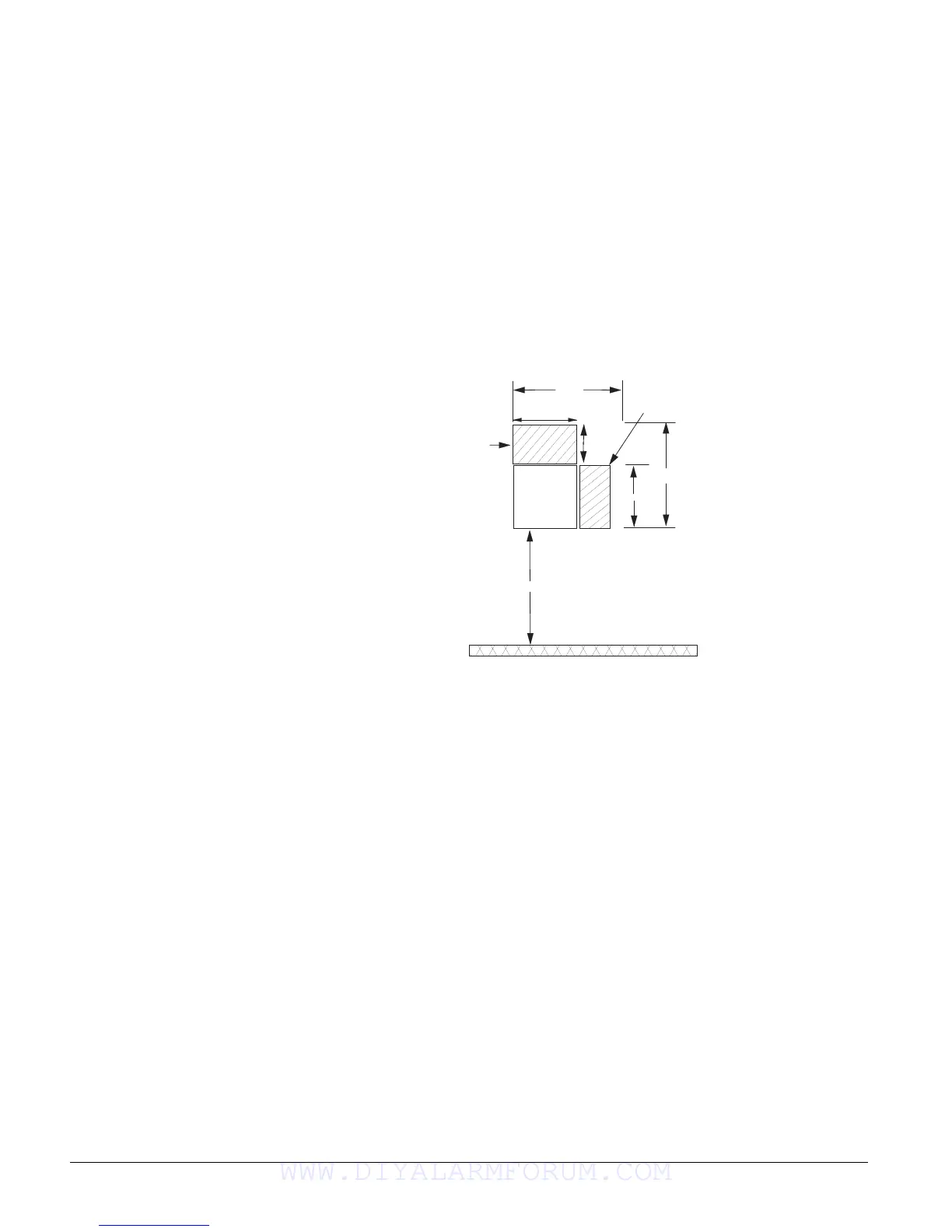
• Mount the panel at a comfortable working height (about 45 to 55 inches from the floor to the
bottom of the panel, as shown in Figure 1).
Figure 1. Determining Panel Location
• Leave space to the left and right of the panel for wiring, phone jack, and mounting optional
modules.
• Allow at least 9 inches above the panel cabinet for antennas.
• Allow at least 24 inches in front of the panel to open the panel door.
Total System Power and Wire Length Guidelines
Power
The panel can supply up to 1 amp (1,000 mA) in full load alarm condition for system devices
connected to panel terminals 4 (+12V), 7 and 8 (speaker terminals), 9 (OUT1), 11 (+12V), 24
(2W SMK ZONE 8), and SnapCard terminals.
For 24-hour backup, the total standby current draw for all devices connected to panel terminals 4
(+12V), 9 (OUT1), 11 (+12V), 24 (if configured for 2-wire smoke loop), and SnapCard terminals
is limited to 90 mA (during normal standby condition) using a 4.5 Ah battery, or 190 mA (during
normal standby condition) using a 7.0 Ah battery.
Wire Length
The total system wire length allowed can vary depending on devices powered by the panel, the
wire length between devices and the panel, and the combined wire length of all devices.
P A N E L
1 9 . 2 5 "
1 2 "
1 4 "
2 3 "
4 5 - 5 5 "
9 "
Antenna
Area
Phone Jack and
Optional Module
Mounting Area
FLOOR
Allow at least 24” in
front of the panel to open
cabinet door and access
panel components.
WWW.DIYALARMFORUM.COM

 Loading...


