Concord 4 Series Systems
11
Note
For best results, it is recom-
mended that you crimp a
spade lug on the wire end at
the panel and secure the lug
to the enclosure as shown in
Figure 5.
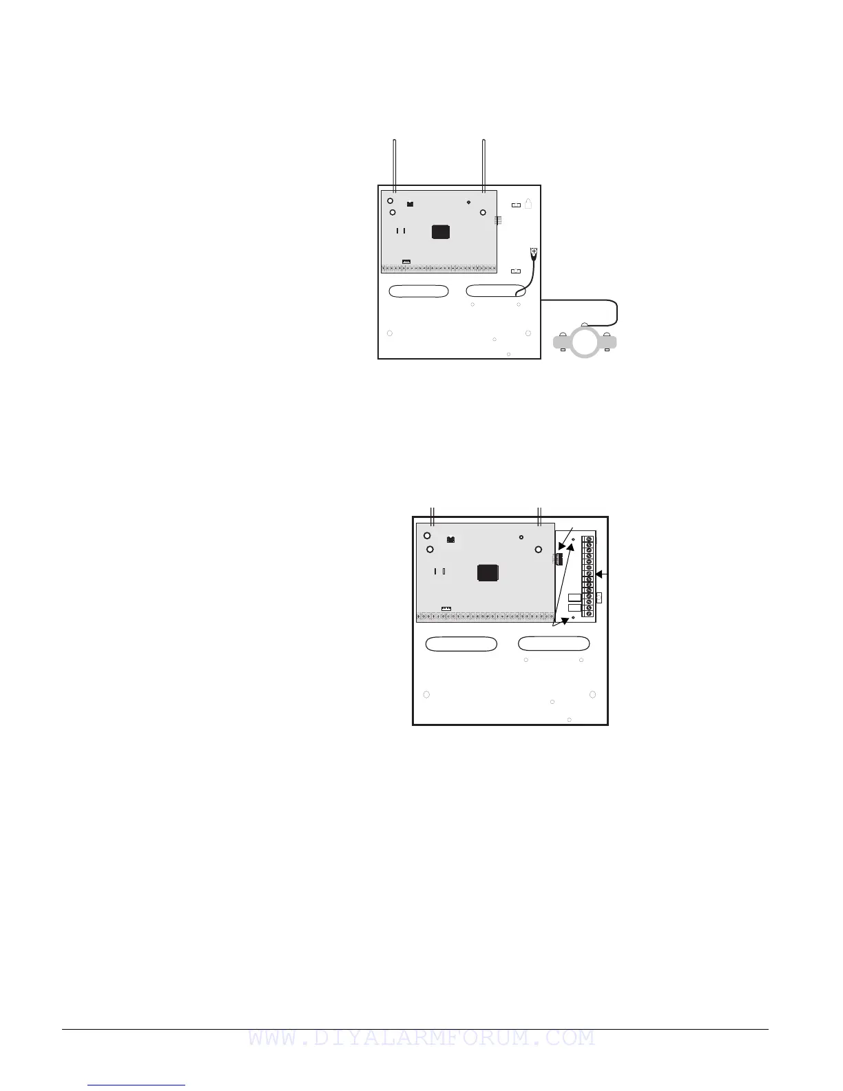
Connecting the Panel to Earth Ground
For maximum protection from lightning strikes and transients, connect the enclosure to earth
ground as shown in Figure 5. Use 16-gauge, solid copper wire from an earth grounded cold water
pipe clamp to the enclosure.
Figure 5. Connecting the Panel to Earth Ground
Installing Optional SnapCards
The SnapCard Header on the right side of the panel allows for the installation of one SnapCard.
Install the desired SnapCard onto the panel SnapCard Header and secure it in place with two
screws, included with the card (see Figure 6).
Connect all necessary input/output wiring using the Installation Instructions included with the
card.
Figure 6. Installing a SnapCard
Note
The panel comes with fac-
tory programmed onboard
hardwire zones. Install
2k-ohm, end of line (EOL)
resistors on all unused fac-
tory programmed onboard
hardwire zones. If you don’t
want to install EOL resistors,
delete any unused zones
from memory. See Table 7
for onboard hardwire zone
factory programming.
Connecting Detection Devices to Panel Zone Inputs
Zone inputs 1 through 8 are supervised using included 2k-ohm, end-of-line resistors at the last
device on each circuit. All eight zones accept either normally open (N/O) or normally closed (N/
C) detection devices.
Connecting Intrusion Detection Devices
Figure 7 shows the typical wiring for N/C and N/O door/window intrusion detection and the typ-
ical wiring for a Detection Systems model DS922 (part no. 13-082) motion detector. The mini-
mum available panel voltage for hardwired PIR motion detectors is 8.5 VDC (9.5 VDC for UL
listed installations).
Note
When using 2-wire smoke detectors on zone 8, the Two-Wire Smoke setting (in program mode) must
be turned on before entering the
LEARN SENSORS menu. See ONBOARD OPTIONS—INPUTS in the section
“Programming the Panel” for complete details.
+
_
To Water Pipe
Pipe
Ground Clamp
+
_
Screw Locations
SnapCard
Header
Connector
SnapCard
WWW.DIYALARMFORUM.COM

 Loading...


