Concord 4 Series Systems 56
Accessory Modules Menu
The ACCESSORY MODULES menu gives you access to the following menus:
•
BUS DEVICES—this menu lets you read bus device unit numbers, assign bus devices to a par-
tition, and configure other features associated with a specific bus device.
•
SNAPCARDS—this menu lets you set the configuration number for each SnapCard output,
assign SnapCard outputs to a partition, and name the SnapCard outputs.
The following describes how to program the settings that appear under
ACCESSORY MODULES—
BUS DEVICES
.
Vox RX Gain (09010)
Audio Verification-Partition 1 (Default = 08)
This setting determines the receiver (talkback) gain
level for voice-activated switching (VOX). Setting
range is 01-10.
If the VOX is switching the speaker on when the
central station operator is not talking, lower this
setting and the VOX Mic Gain setting.
If the VOX is not switching the speaker on when
the central station operator is talking, raise this set-
ting and lower the VOX Mic Gain setting.
To change the VOX RX Gain:
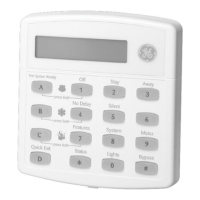
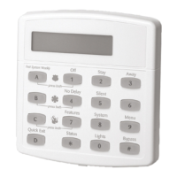
1. With the display showing AUDIO VERIFY OFF/ON, press A or B until
the display shows
VOX RX GAIN nn (current setting).
2. Enter the desired 2-digit setting (01 - 10). The display flashes the
entered setting. Press # and the display shows the new setting.
Unit-ID (10000 thru 10015)
Acc. Modules-Bus Devices (Default = **** or none)
This menu lets you identify all connected bus
devices, view each Unit Number, view the Device
ID number, and configure other settings based on a
specific device. This menu also lets you delete
learned bus devices.
Note
Most settings under ACCESSORY MODULES—BUS
DEVICES have no shortcut numbers.
To help identify bus devices, the 8-digit Device ID
number is also located on a label on each Super-
Bus 2000 device.
To identify bus device Unit and ID:
1. With the display showing BUS DEVICES, press #. The display shows
the bus Unit Number and the 8-digit Device ID number. For exam-
ple:
UNIT - ID 0—02110185. Where 0 is the Unit Number and 02110185
is the Device ID number.
2. Press A or B to identify all other bus Unit Numbers (0–15) and
Device ID numbers.
To delete learned Unit Numbers:
1. With the display showing BUS DEVICES, press #. The display shows
the bus device set to Unit Number 0.
2. Press A or B until the bus device Unit Number you want to delete is
displayed.
3. Press D. The display changes the Unit Number to
NONE.
Device ID
Acc. Modules-Bus Devices-Unit ID-Change ID (Default = none)
This menu lets you change the bus
device ID number when replacing
a defective bus device.
To change a Device ID:
1. With the display showing the desired bus device, press # + #. The display shows
DEVICE ID (current ID).
2. Enter the ID of the new bus device. The display flashes the entered selection. Press #
and the display shows the new setting.
3. Exit programming mode.
4. Remove AC and battery power from the panel.
5. Replace the defective bus device with a new one.
6. Apply AC and battery power to the panel.
WWW.DIYALARMFORUM.COM
 Loading...
