Concord 4 Series Systems 22
4. Connect the green and red wires from the 4-conductor cable to the TIP (+) and RING (-)
posts on the block (see D in Figure 26).
5. Check the phones on the premises for dial tone and the ability to dial out and make phone
calls. If phones do not work correctly, check all wiring and correct where necessary. Proceed
to the “Troubleshooting” section of this manual if problems persist.
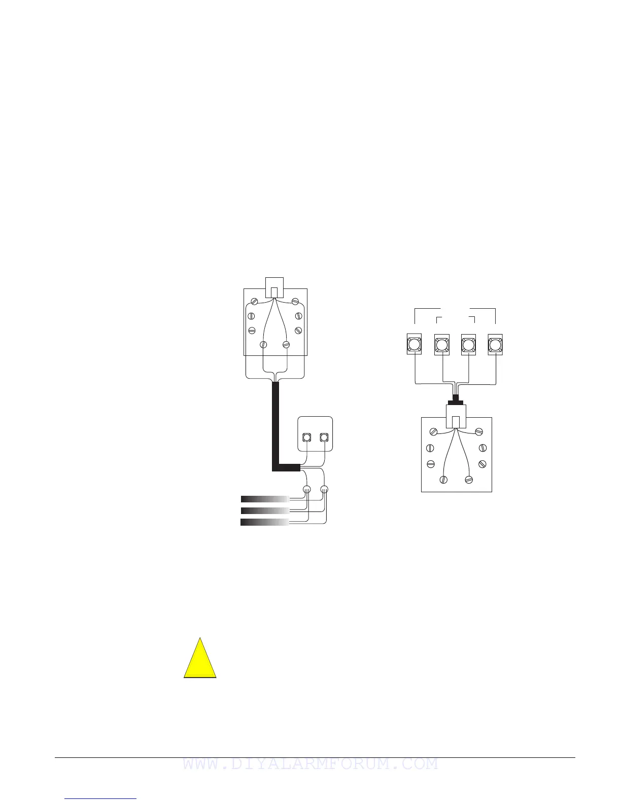
Connecting the Phone Line to the Panel with a DB-8 Cord
After installing the RJ-31X jack, you are ready to connect the phone line to the panel. A DB-8
cord (not included) uses a plug at one end for connecting to the RJ-31X module and flying leads
on the other end for panel terminal connections.
To connect the DB-8 cord to the panel terminals and RJ-31X jack (see Figure 26):
1. Connect the green, brown, gray, and red flying leads from the DB-8 cord to panel terminals
25, 26, 27, and 28.
2. Insert the DB-8 cord’s plug into the RJ-31X.
3. Check the phones on the premises for dial tone and the ability to dial out and make phone
calls. If phones do not work correctly, check all wiring and correct where necessary. Proceed
to the “Troubleshooting” section of this manual if problems persist.
Figure 26. Wiring an RJ-31X Jack and DB-8 Cord to the Panel
Connecting the AC Power Transformer
The panel must be powered by a plug-in stepdown transformer that supplies 16.5 VAC, 40 VA
(600-1023 or 600-1023-CN).
For systems that include X10 Lamp Modules, the panel must be powered with the Line Carrier
Power Transformer that supplies 16.5 VAC, 40 VA (600-1024 or 600-1024-CN). Connect the
power transformer to the panel as shown in Figure 27.
Brn Gry
RJ-31X
Jack
Red
Grn
TELCO
Protector Block
Green
Red
Lines from Phones
on Premises
Dealer
Cable
Run
TIP
(+)
RING
(-)
Black
White
(or Yellow)
Red
Green
Black
White
(or Yellow)
Green
Red
2 5
G R N
2 6
2 7 2 8
B R N
G R Y
R E D
T E L C O
H O U S E
Brn Gry
Grn
Red
DB-8 Cord
RJ-31X
Jack
Green
Brown
Gray
Red
A
B
C
D
Do not plug in the power transformer or connect the backup battery at this time. The
panel must be powered up using the sequence of steps described in the next section,
“Powering Up the Panel.”
Caution
!
WWW.DIYALARMFORUM.COM

 Loading...


