EasyManuals Logo

GE Concord 4 Series Installation Instructions

GE Concord 4 Series
113 pages
To Next Page IconTo Next Page
To Previous Page IconTo Previous Page
Page #15 background imageLoading...
Page #15 background image
Concord 4 Series Systems 10
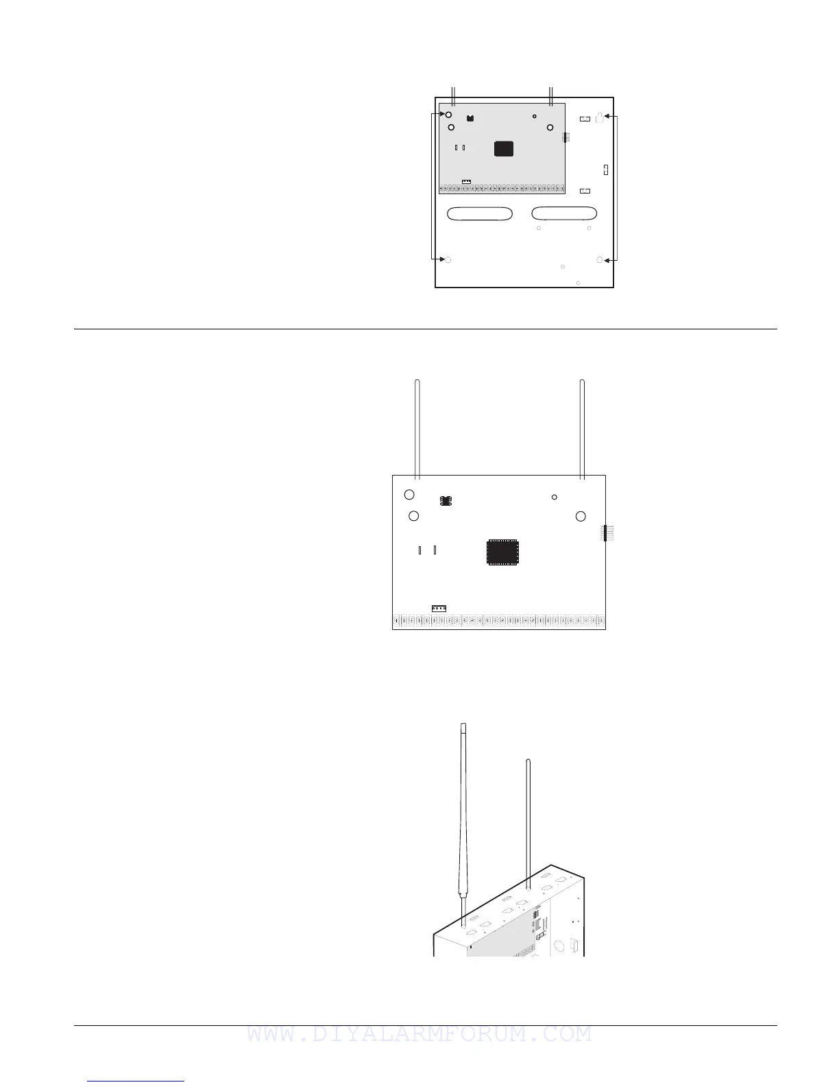
6. Recheck for level, insert the two lower screws, and tighten all four mounting screws.
Figure 2. Mounting the Panel
Identify Panel
Components
Before installing devices and making wiring connections, familiarize yourself with the main
panel components. Figure 3 shows the main component locations.
Figure 3. Circuit Board Main Components
Installing Antenna Shrouds
Note
Skip this step for Concord 4
Hybrid and Concord 4 com-
mercial systems.
Install a plastic antenna shroud (included with panel) over each antenna and snap them into the
holes on top of the enclosure (see Figure 4).
Figure 4. Installing Antenna Shrouds
+
_
Mounting
Holes
Mounting
Holes
+
_
B L K
R E D
Programming
Touchpad
Header
Antennas
Microprocessor
Terminal Strip
EEPROM
SnapCard
Header
Backup Battery
Connections
WWW.DIYALARMFORUM.COM

Table of Contents

Other manuals for GE Concord 4 Series

Questions and Answers:

Question and Answer IconNeed help?

Do you have a question about the GE Concord 4 Series and is the answer not in the manual?

GE Concord 4 Series Specifications

General IconGeneral
User Codes230
Backup Battery12V 4Ah rechargeable battery
Wireless Frequency319.5 MHz
CommunicationPOTS, optional cellular and IP modules
Wireless CapabilityYes
Keypad OptionsMultiple keypad options including touchscreen
Wired Zones8 on board
Power Supply16.5 VAC Transformer
CompatibilityCompatible with GE Security wireless sensors
ZonesUp to 96
Event Buffer512

Related product manuals