Concord 4 Series Systems
9
Note
When installing SuperBus 2000 RF Receiver Modules, the Antenna Tamper feature must be set to off
(see REPORTING—GLOBAL in the “Programming” section).
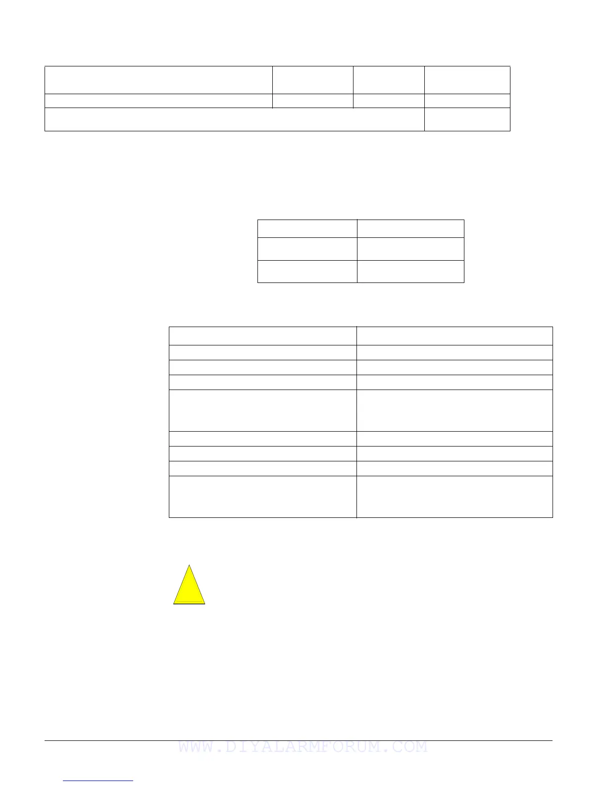
Table 2 describes the total system wire lengths allowed for all SuperBus 2000 devices when
installing systems using unshielded or shielded cable. (The maximum wire length for individual
devices is shown in Table 1)
After determining panel location, run all necessary wires to that location using the guidelines in
Table 3.
Mounting the Panel
Use the following procedure to mount the panel to the wall or wall studs.
Make sure you are free of static electricity whenever you work on the panel with the cover
open. To discharge any static, first touch the metal panel chassis, then stay in contact with
the chassis when touching the circuit board. Using an approved grounding strap is recom-
mended.
To mount the panel (see Figure 2):
1. Remove the panel door and remove the necessary wiring knockouts. Be careful not to dam-
age the circuit board.
2. Feed all wires through wiring knockouts and place the panel in position against the wall.
3. Level the panel and mark the top and bottom mounting holes.
4. Install anchors where studs are not present.
5. Partially insert screws into the two top mounting hole locations, then hang the panel on the
two screws.
Speaker Siren (60-528 or 13-060) 18 ga.—100 ft. 0 mA 500 mA
*Maximum current draw for the SnapCards does not include the load which may be applied to
their auxiliary DC supply.
Table 1: Maximum Device Wire Length and MIn./Max. Current Draw (Continued)
Device
Max. Wire Length
to Panel
Standby mA
Draw
Alarm mA Draw
Table 2: Total System Wire Length Allowed
Wire Type Total System Wire
18-gauge, unshielded
18-gauge, shielded
4,000 ft.
3,000 ft.
22-gauge, unshielded
22-gauge, shielded
4,000 ft.
3,000 ft.
Table 3: Wire Requirements
Device Wire Requirements
AC Power Transformer 2-conductor, 18-gauge, 25 feet max
Earth Ground Single conductor, 16-gauge solid, 25 feet max
Telephone (RJ-31X) 4-conductor
Detection Devices
2- or 4-conductor, 22-gauge, 1,000 feet max
2- or 4-conductor, 18-gauge, 2,500 feet max
(based on 30 ohms max loop resistance includ-
ing device)
Speakers 2-conductor, 18-gauge, 100 feet max
SuperBus 2000 Devices 4-conductor, 22- or 18-gauge (see Table 1)
Interrogator 200 AVM Power and Microphone 4-conductor, 22-gauge, shielded (see Table 1)
2-Wire Smoke Detectors
2-conductor, 22-gauge, 330 feet max
2-conductor, 18-gauge, 830 feet max
(based on 10-ohms max loop resistance plus a
2k-ohm, end-of-line resistor)
Caution
!
WWW.DIYALARMFORUM.COM

 Loading...


