Concord 4 Series Systems 18
Note
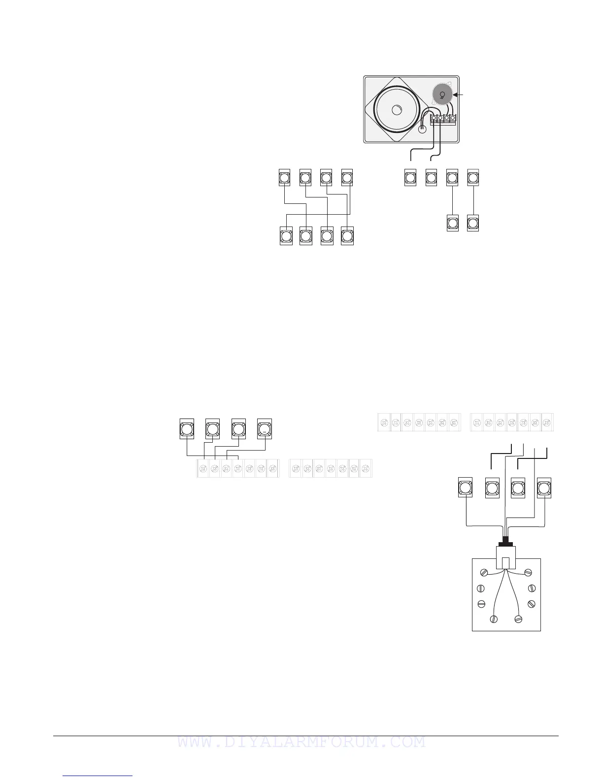
In UL Listed installations, the
Voice Only Module is for
supplementary use only.
The module requires panel power and bus connections, and speaker connection through panel
terminals as shown in Figure 18.
Figure 18. Wiring for the Voice Only Module
Note
For RJ-31X connections,
see “Installing an RJ-31X
Phone Jack (13-081).
SuperBus 2000 Phone Interface/Voice Module (60-777-01)
The Phone Interface/Voice Module includes two backplates for mounting the module inside the
control panel cabinet. The module can also be mounted outside of the control panel using an
optional plastic housing (part no. 60-800). Refer to the SuperBus 2000 Phone Interface/Voice
Module Installation Instructions included with each module, for complete mounting instructions.
Note
In UL Listed installations, the
Phone Interface/Voice Mod-
ule is for supplementary use
only.
The module requires panel power and bus connections, phone line connection through panel ter-
minals and DB-8 cord (from an RJ-31X jack), and speaker connection through panel terminals.
Connect the module to the panel power and bus terminals as shown in Figure 19.
For partition 1, connect the phone line to the module through the panel terminals and DB-8 cord
(from an RJ-31X jack) as shown in Figure 19. For partitions 2-6 phone connections, see the
SuperBus 2000 Phone Interface/Voice Module Installation Instructions.
Figure 19. Wiring for the Phone Interface/Voice Module
Note
To prevent status voice mes-
sages from being broadcast
outside, do not connect
exterior speakers to Phone
Interface/Voice module ter-
minals 6 and 7.
Wiring for Status Voice Messages Only
Connect an interior speaker to the Phone Interface/Voice Module terminals as shown under “Sta-
tus” in Figure 20. When connected as shown, the speaker only produces status voice messages.
In an alarm, the speaker announces voice status messages.
1 2
3 4
5 6
7 8
+ 1 2 V
B U S
A
B U S
B
S P K 1
A U D 2
G N D
S P K 2 A U D 1
4 5
6
A
B
3
G N D + 1 2 V
B U S
7
8
S P E A K E R
Module
Terminals
Module
Terminals
Panel
Terminals
Panel
Terminals
Hardwire Interior
Speaker (60-528)
Not Used
1
+ 1 2 V
2
A
3
B
4
G N D
5
G N D
6
S P K 1
7
S P K 2
8
A U D 1
9
A U D 2
1 0
G N D
1 1
T I P 1
1 2
T I P 2
1 3
R I N G
2
1 4
R I N G
1
2 5
G R N
2 6
2 7 2 8
B R N
G R Y
R E D
Module Terminals
Panel Terminals
RJ-31X Jack
Grn
Red
Brn
Gry
DB-8 Cord
Green
Red
Brown
Gray
3 4 5
6
+ 1 2 V
A B U S B
G N D
1
+ 1 2 V
2
A
3
B
4
G N D
5
G N D
6
S P K 1
7
S P K 2
8
A U D 1
9
A U D 2
1 0
G N D
1 1
T I P 1
1 2
T I P 2
1 3
R I N G
2
1 4
R I N G
1
Panel Terminals
Module Terminals
WWW.DIYALARMFORUM.COM

 Loading...


