Concord 4 Series Systems
17
SuperBus 2000 2 Amp Power Supply (600-1019)
Refer to power supply installation instructions for the mounting procedure.
Note
Do not connect power (AC
and battery) to the power
supply until the panel is
ready for power up. For
power supply AC and bat-
tery connections, see the
SuperBus 2000 2 Amp
Power Supply Installation
Instructions.
Connect the power supply to the panel terminals and devices to be powered as shown in Figure
16.
Figure 16. Wiring the SuperBus 2 Amp Power Supply to the Panel
SuperBus 2000 Transceiver Module (600-1025-01-95R) and SuperBus 2000
RF Receiver Module (60-764-95R-01)
Note
When installing SuperBus
2000 RF Receiver Modules,
the Antenna Tamper feature
must be set to off (see
REPORTING—GLOBAL in
the “Programming” section).
The transceiver and receiver expand RF reception range when placed in the vicinity of sensors on
the fringe of panel RF reception.
Refer to trasceiver or receiver installation instructions for the mounting procedure.
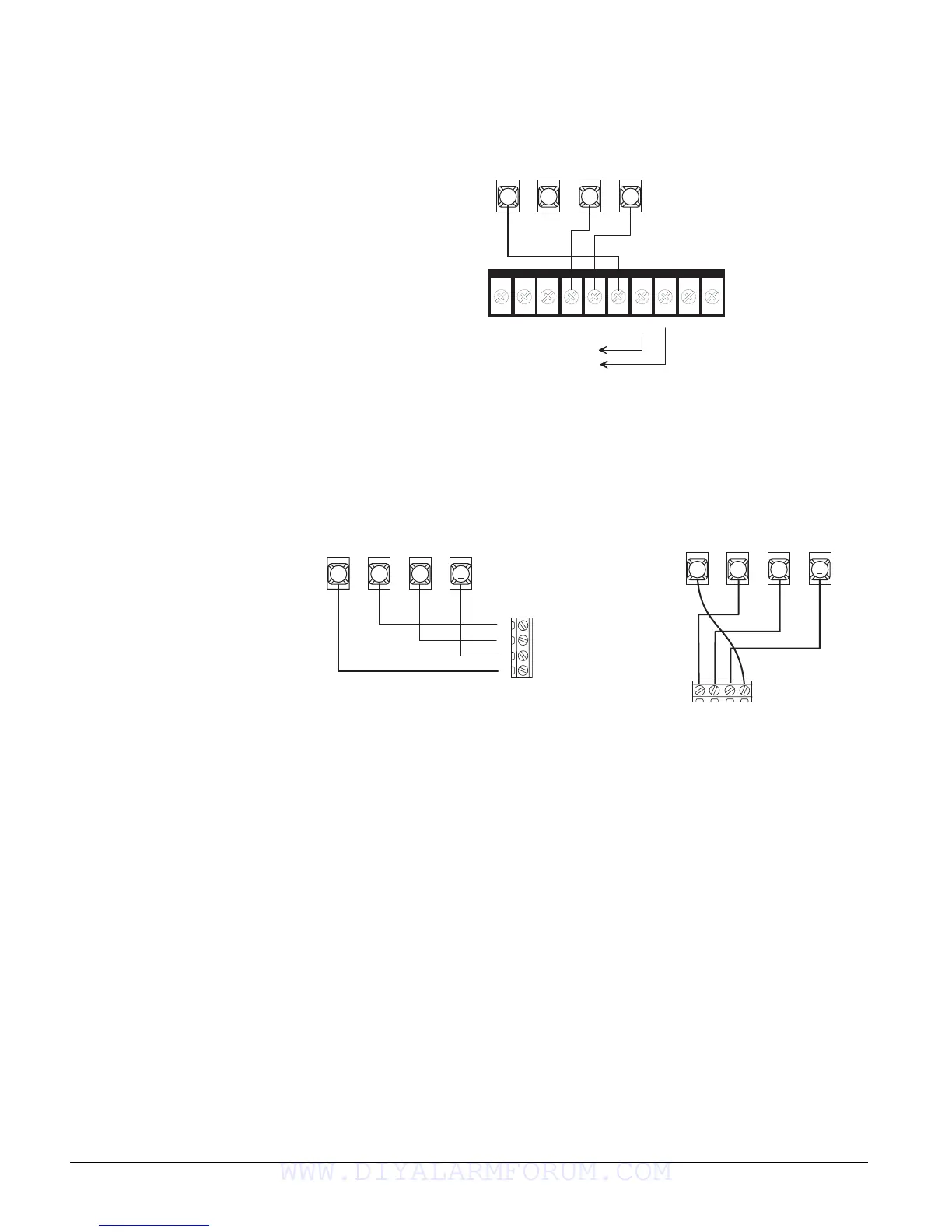
Connect the transceiver and receiver (up to four total) to the panel as shown in Figure 17.
Figure 17. Wiring the SuperBus 2000 RF Transceiver and RF Receiver to the Panel
SuperBus 2000 Voice Only Module
The module can be mounted inside or outside of the control panel cabinet. Refer to the SuperBus
2000 Voice Only Module Installation Instructions included with each module, for complete
mounting instructions.
2 4 V A C
2 4 V A C + 1 2 V
B U S A
B U S B
G N D
+ 1 2 V
O U T
Z O N EG N D
G N D
3 4 5
6
+ 1 2 V
A
B
G N D
B U S
N O C O N N E C T I O N
Panel
Terminals
Power Supply
Terminals
To power inputs
on devices
3 4 5
6
+ 1 2 V
A
B
G N D
B U S
+ 1 2 V
A
B
G N D
Panel
Terminals
Transceiver
Terminals
3 4 5
6
+ 1 2 V
A
B
G N D
B U S
+ 1 2 V
A
B
G N D
Receiver
Terminals
Panel
Terminals
WWW.DIYALARMFORUM.COM

 Loading...


