Concord 4 Series Systems
53
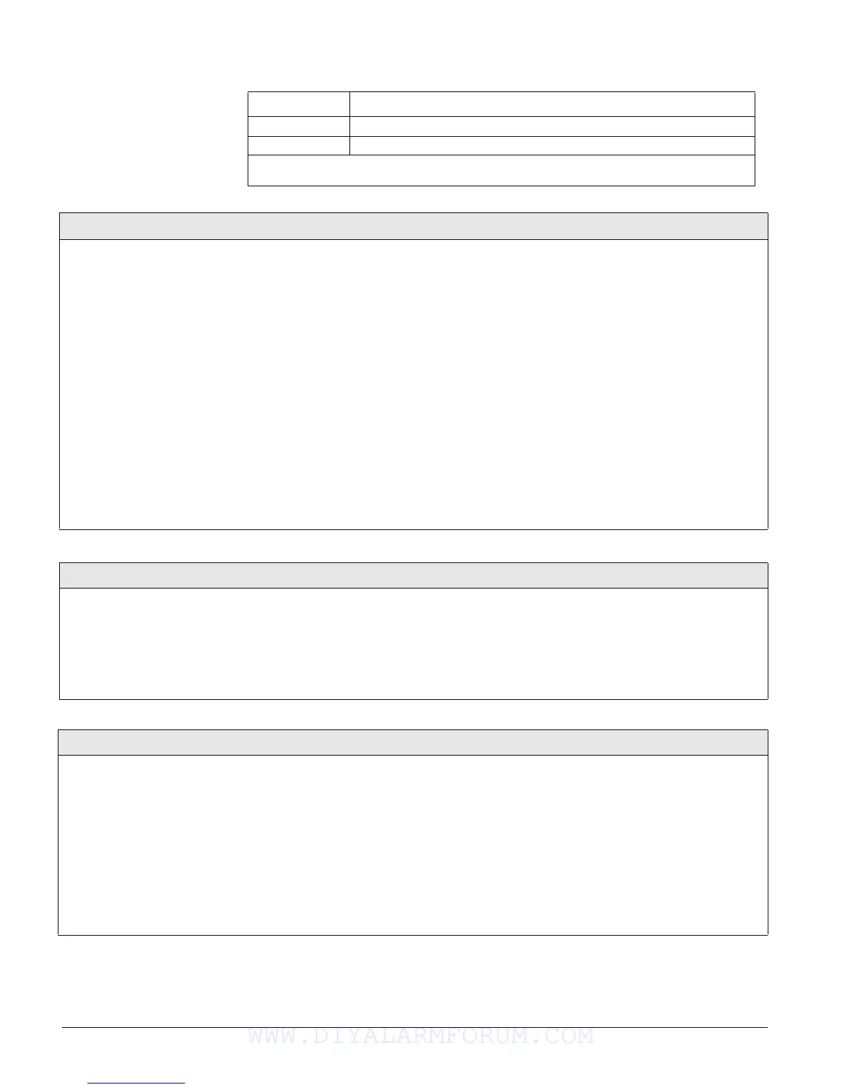
7 13–Instant Perimeter
8 13–Instant Perimeter
Note
If the panel memory is cleared, all onboard hardwire zone factory programming will be erased.
Table 7: Onboard Hardwire Zone Factory Programming
Zone Input Group No. & Description
Sensor Text (081)
Sensors (Default = none)
Use the following guidelines to “name” zone and sensor loca-
tions:
• Use the item numbers that appear in Appendix B, Table B2
“Item Numbers and Sensor Text” for characters and words
listed there.
• If a desired word does not appear in Table B2, create it
using the characters (custom text).
• When using words from Table B2, spaces between them
appear automatically. When using characters from Table
B2 to create words, you must reserve an item number for a
‘space’ after the word.
• Each character or word uses up one item number. For
example, a word from the list counts as one item number.
A created word (such as BOY’S) counts as six item num-
bers—4 letters, 1 apostrophe, and 1 space.
• Only 16 item numbers are allowed for each zone or sensor
name, so plan ahead before programming sensor text. You
may need to abbreviate words to avoid running out of item
numbers.
To program Sensor Text:
1. Press A or B until the display shows SENSOR TEXT.
2. Press # and the display shows
TEXT FOR SN 01.
3. Press A or B until the display shows the desired sensor
number (or enter the desired sensor number and press #).
4. Press # and the display shows:
SN 1 ITEM 0 0 - ________.
Where ITEM 0 is the first character/word location and 0 is
the character/word number.
5. Enter the number of the desired character or word, or
scroll through the numbers by pressing B (forward) or A
(backward). If you make a mistake, simply enter the cor-
rect number or continue scrolling through choices.
6. Press # to accept the displayed choice and the display
shows:
SN 1 ITEM 1 0 -.____
7. Repeat steps 5 and 6 as needed to complete the zone or
sensor name.
8. Press * after entering the last character or word number.
The display shows the complete text name. For example:
TEXT FOR SN 01 FRONT ENTRY DOOR
Delete Sensors (082)
Sensors (Default = none)
The following procedure describes how to remove hardwire
zone and wireless sensor numbers from panel memory.
Note
Deleting sensors does not delete sensor text associated with the
deleted sensor number. To delete sensor text, enter the
SENSOR
TEXT menu and enter 000 (nulls) for each item number.
To Delete Sensors from panel memory:
1. Press A or B until the display shows DELETE SENSORS.
2. Press # and the display shows
DELETE SENSOR nn (lowest
zone/sensor number in panel memory).
3. Press # to delete the displayed sensor or—enter the
desired sensor number, then press #.
4. Repeat steps 2 and 3 until all desired sensors are deleted.
Edit Sensors (083)
Sensors (Default = none)
This menu lets you view and, if desired,
change the group and partition assignment for
each learned zone or sensor. For example, the
display shows:
S01 P1 G13 NC HW BACK DOOR.
Where: S01 = zone/sensor number, P1 = parti-
tion 1,
G13 = sensor group 13, NC = normally
closed, HW = hardwired, and BACK DOOR is the
programmed text name.
Other description codes include,
RF = wireless
sensor,
TP = touchpad, NO = normally open.
To Edit Sensors:
1. Press A or B until the display shows EDIT SENSORS.
2. Press # and the display shows the sensor or zone with the lowest number.
3. Press A or B to scroll through all learned zones and sensors.
4. When the desired zone or sensor is displayed, press #. The display shows
SENSOR PTN n (current partition assignment).
5. Enter the desired partition number, then press #. The display shows the
new partition assignment.
6. Press A or B and the display shows
SENSOR GROUP nn (current group
assignment).
7. Enter the desired group number, then press #. The display shows the new
group assignment.
WWW.DIYALARMFORUM.COM

 Loading...


