[EN] English - K0449 Instrument parts, accessories and options 1-1
Chapter 1: Instrument parts,
accessories and options
1.1 Introduction
This chapter gives a description of the different parts of the
instrument and the accessories/options available.
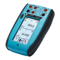
1.2 The instrument
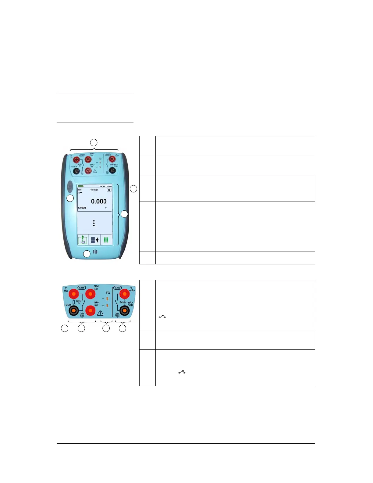
1. On or off button. Press and hold the button down until the
display comes on.
2. Channel 1 (CH1) and channel 2 (CH2) connectors for
electrical operations; see Figure 1-2.
3. Rubber pull-down cover for the USB type A connector; USB
mini type B connector and +5V DC power input socket;
see Figure 1-3.
4. Colour display with touch-screen. The number of windows
you see on the display is set by the number of task selections
and external modules you are working with (maximum: 6);
see Section 2.9 (Display operation).
To make a selection, lightly tap on the applicable display area
with a finger.
5. Sealed speaker unit.
1
2
5
3
4
Figure 1-1: General view of
the instrument
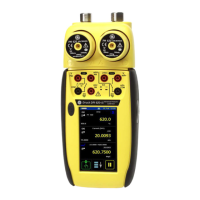
2a Channel 1 (CH1) connectors for:
V: volts/mV DC or AC*; Hz: frequency and counts/min,
counts/hour (cpm/cph);
::resistance; RTD: 2-wire,
3-wire (3W), 4-wire (4W) resistance temperature detectors;
: switch operation; mA+, mA-: current. Refer to
Chapter 3 (Electrical and IDOS operations).
2b Channel 1 (CH1) connectors for thermocouples (TC). Refer to
Chapter 3.
2c Isolated channel 2 (CH2) connectors for:
V: volts/mV DC; mA+, mA-: current; 24Vo: 24V loop power
supply; : switch operation; refer to Chapter 3. For HART
connections, refer to Chapter 8.
(COM = Common) Note: * You can measure an AC voltage (maximum: 20 Vrms)
without the GE specified AC probe (P/N IO620-AC). If it is more than
20Vrms, you must use the AC probe (maximum: 300 Vrms) in CH1
connectors V/Hz and COM; see Section 3.2.5.
Figure 1-2: CH1/CH2
connections
2 b ca
 Loading...