[EN] English - K0449 Pressure indicator operation (MC 620) 4-1
Chapter 4: Pressure indicator
operation (MC 620)
4.1 Introduction
This section gives examples of how to connect and use the
instrument to measure pressure with the module carrier
(MC 620) and the applicable pressure modules (PM 620).
To measure pressure with the IDOS UPM, refer to Chapter 3.
To make a fully integrated pressure calibrator instrument with
one of the three pressure stations, refer to the user manual for
the PV 62x series of pressure stations - K0457
Before you start:
• Read and understand the “Safety” section.
• Do not use a damaged instrument.
Note: Use only original parts supplied by the manufacturer.
4.2 Parts and
assembly
This figure shows the parts of the module carrier (MC 620) and
pressure module (PM 620).
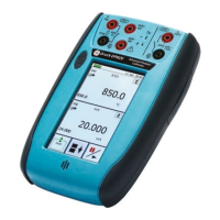
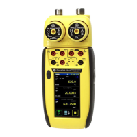
When you attach these items to the DPI 620 calibrator, you
have a fully integrated pressure indicator that can measure
pneumatic or hydraulic pressure.
Caution: To prevent damage to the PM 620
module, only use it within the specified pressure
limit on the label.
1
2
3
4
1
2
3
b) PM 620
a) MC 620
5
a
1. Pressure connection (G1/8 or 1/8NPT) to attach
external pressure equipment.
2. Pressure and electrical connections for a pressure
module (PM 620). These are self-sealing pressure
connections.
3. Two screws to attach the calibrator (DPI 620).
4. Electrical connections for the calibrator (DPI 620).
5. Pressure module (PM 620) with a pressure
connection, reference port (a) and a label. The
label includes:
Pressure range. Example: 20 bar g (g: gauge;
a: absolute); serial number (S/N); manufacturer:
name, address, website

 Loading...
