[EN] English - K0449 Electrical and IDOS operations 3-7
Issue 1
2. Complete the electrical connections.
3. If necessary change the Source Settings and continue with
source operation.
Values to set:
Waveform (Square, Triangle, Sine);
Amplitude (Amplitude value)
4. Automation: Set the applicable output value; see
Section 2.11.2.
3.2.9 Example procedure: Measure or simulate an RTD (or Resistance)
These examples (A and B) show Channel 1 (CH1) set up to
measure or simulate an RTD. A 4-Wire configuration gives the
best accuracy; a 2-Wire configuration has the lowest accuracy
(4-Wire RTD shown).
Note: To measure or simulate resistance (
:), set the
Resistance function
Example A 1. Set the applicable software options; see Section 3.2.1
(Procedure overview).
2. Complete the electrical connections.
3. If necessary change the Settings and continue with the
measure operation.
21
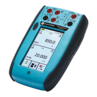
Measure an RTD on
channel 1 (CH1)
Range: 850 °C
RTD Type: PT100
Connection: 4 wire
A
3
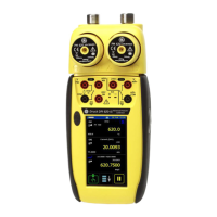
Simulate an RTD on
channel 1 (CH1)
Range: 850 °C
RTD Type: PT100
Connection: 4 wire
Automation: Nudge
(Section 2.11.2)
2
B
4
1
3
 Loading...