Issue 1
ii
Quick reference data
Copyright
© 2008 General Electric Company. All rights reserved.
Trademarks Microsoft and Windows are either registered trademarks or
trademarks of Microsoft Corporation in the United States and/or
other countries.
HART is a registered trademark of the HART Communications
Foundation.
All product names are trademarks of their respective
companies.
A1.1
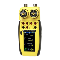
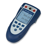
DPI 620: Channel 1 (CH1)
Measure (M) / Source (S) / Power (P)
±30 V (M) ±55 mA (M)
0 to 12 V (S) 0 to 24 mA (S)
±2000 mV (M) 8 RTDs (M/S): Pt1000, Pt500, Pt200, Pt100(385),
0 to 2000 mV (S) Pt50, D 100, Ni 100, Ni 120
0 to 4000 : (M/S) 12 Thermocouples (M/S): K, J, T, B, R, S, E, N, L, U, C, D
0 to 50 kHz (M/S) 20 Vrms (M): voltage connectors on CH1 only.
Switch (M) 2000 mV rms (M): voltage connectors on CH1 only.
300 Vrms, 50 Hz to 400 Hz (M).
Only with the AC probe; see
Section 3.2.5.
A1.2
DPI 620: Channel 2 (CH2)
±30 V (M) 0 to 24 mA (S)
±2000 mV (M) 24 V loop (P); maximum: 24 mA
±55 mA (M) Switch (M)
A1.3
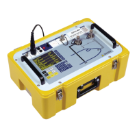
DPI 620 + MC 620 + PM 620
Pressure* (M)
Gauge: 25 mbar to 200 bar (0.36 to 3000 psi)
Absolute: 350 mbar to 1000 bar (5 to 15000 psi)
Note: Maximum pneumatic pressure: 500 bar (7250 psi)
*Caution: To prevent damage to the PM 620 module, only use it within the specified
pressure limit on the label.
 Loading...