Issue 1
4-2 Pressure indicator operation (MC 620) K0449 - [EN] English
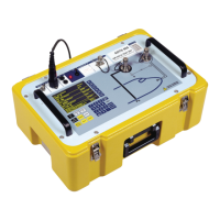
4.2.1 Assembly instructions
4.3 Pressure
connections
WARNING: Pressurized gases and fluids are dangerous.
Before you attach or disconnect pressure equipment,
safely release all the pressure.
The pressure ports for external equipment use “Quick fit”
pressure adaptors; see Section 1.4 (Accessories). These are
easy to remove, change and install.
4.3.1 Procedure (to attach external equipment)
a
b
4
3
2
1
Step Procedure
1. Align the two slots (a) on the calibrator with the two
posts (b) on the module carrier.
2. When the posts are fully engaged in the slots,
tighten the two screws until they are hand tight.
3. Attach one or two PM 620 modules with the correct
range and type.
4. Tighten each one until it is hand tight only.
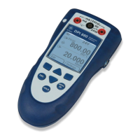
When this symbol flashes at the top of the display, it
shows there is communication between the module
and the calibrator.
Step Procedure
1. Remove the adaptor from the pressure port.
2. Use an applicable seal for the pressure connection:
a. NPT type: Use an applicable sealant on the thread.
b. BSP (parallel) type: We recommend a bonded seal
at the bottom.
c. BSP (parallel) type, 100 bar (1500 psi) or less: a
bonded seal at the top is permitted.
3. Attach the adaptor to the external equipment; if
necessary use one of the alternative adaptors in
Section 1.4 (Accessories), then tighten to the applicable
torque.
Continued
1
2
NPT
a.
c.
(G) / BSPP
Pd 100 bar
b.
(G) / BSPP
3
 Loading...