MDS 05-6632A01, Rev. F MDS Orbit MCR/ECR Technical Manual 27
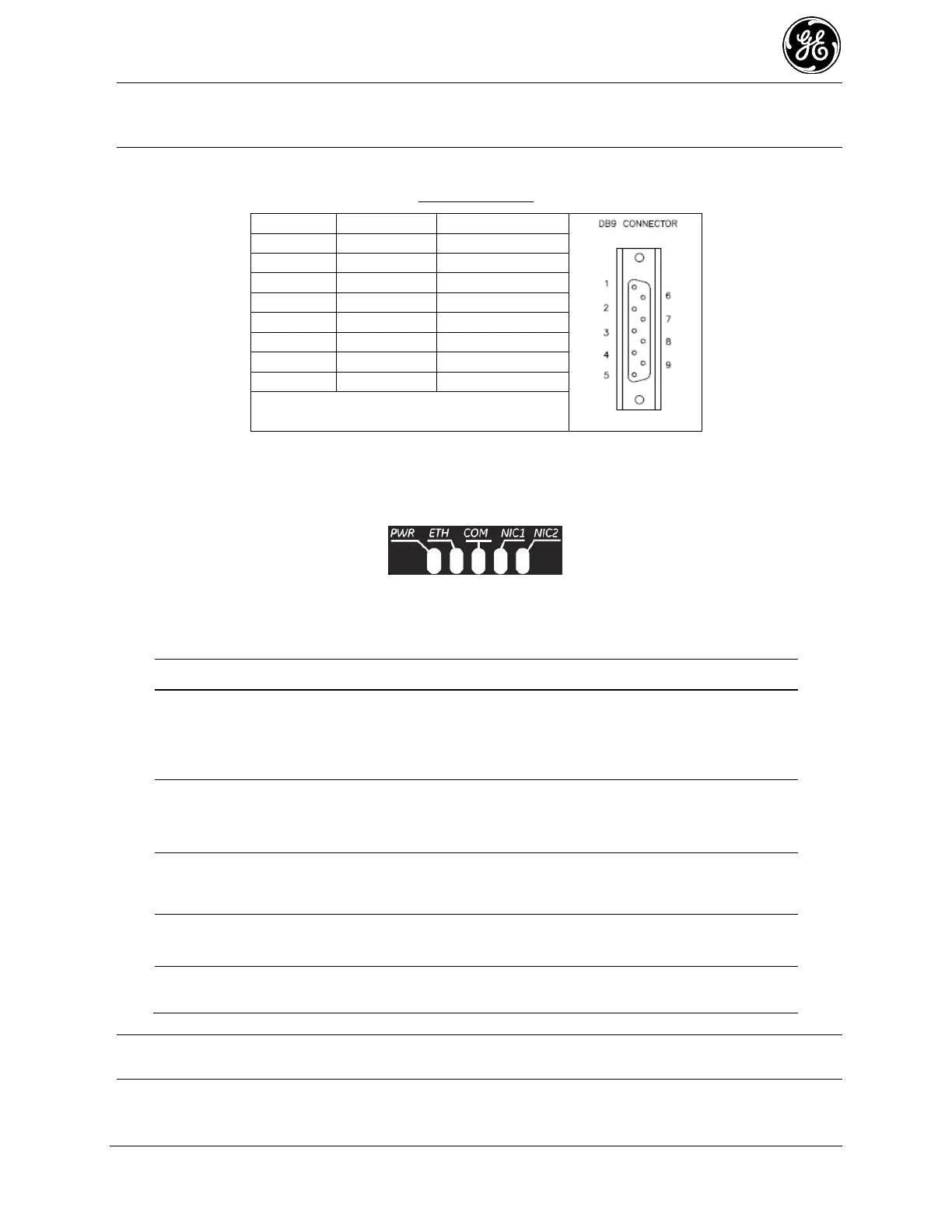
NOTE GE MDS part number 73-2434A25 provides a custom RJ45 to DB9 Adapter for use with the
Orbit MCR and other GE MDS products. The chart below provides details for connections
made using this adapter.
WIRING CHART
LED Status Indicators—The LEDs on the unit provide visual indications of the status of the device as
shown in the following chart:
Figure 2-6. LED Status Indicators
Table 2-4. Description of LED Status Indicators
Off
Solid Green
Fast Blink/Red (1x/sec.)
No power to unit
Unit is powered, no problems detected
Alarm indication
Off
Solid Green
Blinking Green
No Ethernet link to network
Ethernet link present
Ethernet traffic in/out
No serial connection, or idle
Serial traffic in/out
Interface disabled
Interface enabled
Interface disabled
Interface enabled
NOTE In addition to the LEDs above, the Ethernet connector has two embedded LEDs. A yellow
indicates a link at 100 Mbps operation. A flashing green indicates Ethernet data traffic.
 Loading...