MDS 05-6632A01, Rev. F MDS Orbit MCR/ECR Technical Manual 381
4.0 TECHNICAL REFERENCE
4.1 Troubleshooting
All units must meet the basic requirements listed below for proper operation. Check these items first
when troubleshooting a system problem:
Adequate and stable primary power
Secure connections (antennas, data and power)
A clear transmission path between associated units
An efficient, properly installed antenna system
Proper configuration of unit settings
Correct interface between the unit and other equipment
LED Status Indicators 4.1.1
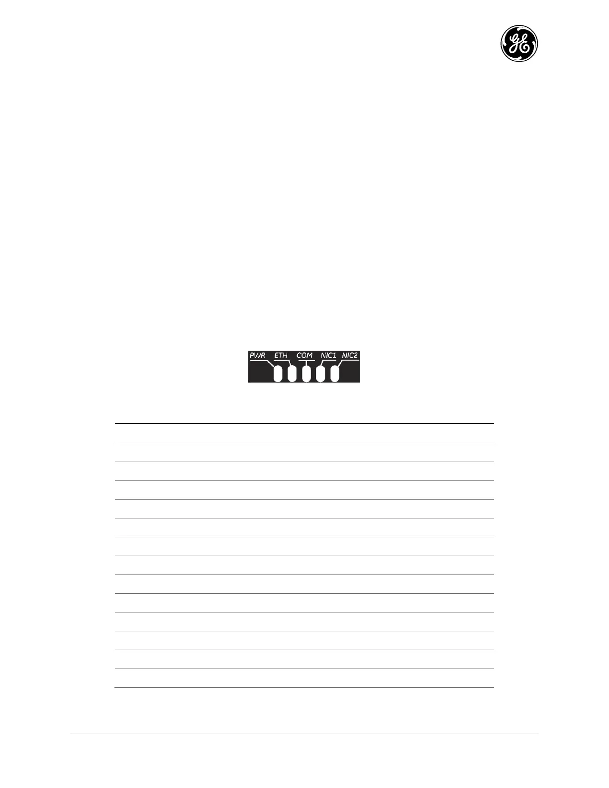
The LEDs on the unit are visual indications of the status of the device. These indicators can provide
useful information when troubleshooting. Refer toTable 4-3, Table 4-4, Table 4-5, and Table 4-6.
Depending on the interfaces ordered, the NIC1 and NIC2 slot can be populated with a Cellular modem, a
WiFi interface, an LnRadio interface or an NxRadio interface. Described in Table 4-1 below, are the
possible NIC1 and NIC2 LED combinations based on the product configuration ordered.
Figure 4-1. LED Status Indicators
Table 4-1. NIC LED Descriptions
Lic. Narrowband (LnRadio)
Lic. Narrowband (LnRadio)
Lic. Narrowband (LnRadio)
Lic. Narrowband (LnRadio)
 Loading...