32 MDS Orbit MCR/ECR Technical Manual MDS 05-6632A01, Rev. F
Antenna Type and Orientation (Cell & Wi-Fi)
It is important to use antennas designed to operate in the applicable cellular coverage bands with a Return
Loss of 10 dB or better. Placement of the antennas also plays a key role in the coverage of the system.
While the antennas can be placed directly on the face of the unit in some short range installations, the best
performance is obtained when mounting antennas remotely using low loss coaxial cable. Antennas
mounted in close proximity to each other can couple signals between them and desensitize the RF
module.
When placing the indoor SMA style “paddle” antennas on the face of the unit, position them with a 90
degree angle of separation to improve the isolation. A “V” or an “L” configuration is a common approach
to use with the Main channel typically mounted for vertical polarization. The multipath nature of Cellular
systems means that polarization for indoor use is not normally a critical factor. Isolation between the
antennas is more important.
Note that with any installation, there needs to be a minimum 20 cm spacing between all transmit antennas
to avoid co-location difficulties.
Indoor use case:
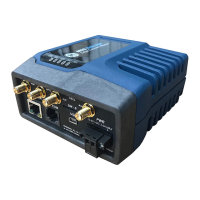
This scenario employs direct mounting of an LTE paddle antenna (GE MDS PN: 97-2485A04) on the
Main and Aux Cell channels and cabled mounting of the Wi-Fi antenna (GE MDS PN: 97-4278A34)
using a magnetic mount (GE MDS PN: 97-4278A78). This configuration offers easy mobility for
evaluation purposes or indoor applications with good cellular signal coverage (see Figure 2-11).
Figure 2-11. Direct Mounting of Cell Antenna; Cabled WiFi Antenna
Minimum 8-inch (20.32 cm) separation between cell and WiFi antennas
This arrangement employs cabled mounting of the LTE paddle antennas (GE MDS 97-2485A04) on the
Main and AUX Cell channels and cabled mounting of the Wi-Fi antenna (GE MDS 97-4278A34) using a
magnetic mount (GE MDS 97-4278A78). The Wi-Fi antenna may also be directly attached to the unit, if
desired. This configuration works well for indoor installations in equipment closets, or for more
permanent applications.
Outdoor use case:
External enclosures—If the system is going to be installed in a weathertight enclosure and mounted
outside in the elements, cabled use of external LTE antennas (GE MDS PN: 97-2485A05) on the Main
and AUX Cell ports, with cabled use of the External Wi-Fi antenna (GE MDS PN: 97-4278A48) is a
good solution. This configuration requires a suitable metallic ground plane for the Cellular antennas (8"
diameter disc minimum for the 97-2485A05 series) or a suitable counterpoise for frequencies as low as
698 MHz Metal enclosures work well for ground plane requirements, when ground contact inside the box
is not impeded by painted surfaces.
Do not use internally mounted antennas inside of metal enclosures.
Other antenna configurations can be easily customized for applications not listed here. Consult your
factory representative for installation matters.

 Loading...