EasyManua.ls Logo

GE RSTi-EP

GE RSTi-EP
425 pages
To Next Page IconTo Next Page
To Previous Page IconTo Previous Page
Loading...
Chapter 5 Detailed Descriptions of I/O Modules
GFK-2958E RSTi-EP User Manual 101
Process Data Inputs EP-1218
Byte
Bit
Description
IB0
IX0.0
DI0
IX0.1
DI1
IX0.2
DI2
IX0.3
DI3
IX0.4
DI4
IX0.5
DI5
IX0.6
DI6
IX0.7
DI7
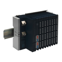
5.3 Digital Input Module EP-1318
Digital Input Module EP-1318 Connection Diagram EP-1318
The digital input module EP-1318 can detect up to 8 input signals. Two sensors can be connected to
each connector using a 2-wire or 3-wire connection. A status LED is assigned to each channel. The
module electronics supply the connected sensors with power from the input current path (I
IN
).

Table of Contents

Other manuals for GE RSTi-EP

Related product manuals