GFK-2958E RSTi-EP User Manual 160
5.14 Digital Output Module EP- 5111
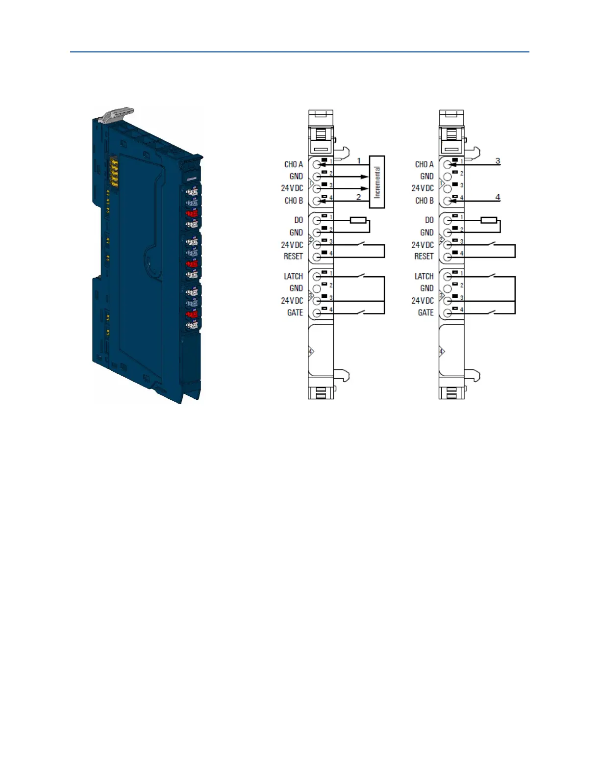
Counter Module EP-5111 Connection Diagram EP-5111
In reference to the Connection Diagram:
1 Track A
2 Track B
3 Cycle
4 Direction 0/1 (24 V)
• One 32-bit counter (AB) invertible, 24 V DC
• Counting frequency 100 kHz max (AB 1/2/4-times sampling or pulse and direction)
• Latch value, comparison value, setting value, input filter (parametrizable)
• HW gate reset, digital output for comparison
• Alarm and diagnostic function with μs time stamp
• μs time stamp for counting value (for example, for speed measurements)

 Loading...


