GFK-2958E RSTi-EP User Manual November 2017 7
Introduction
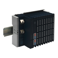
This manual describes the RSTi-EP remote I/O system. The products of the RSTi-EP series are
intended for use in industrial automation. A RSTi-EP station with network adapter and connected
modules is intended for the decentralized control of systems or sub-systems. Via the network
adapter every module of a station is integrated into a fieldbus structure and connected to the
primary control unit. The RSTi-EP products conform to protection class IP 20 (in accordance with DIN
EN 60529), they can be used in potentially explosive atmospheres rated as Zone 2 (as per Directive
2014/34/EU) and in safe zones.
The observance of the supplied documentation is part of the intended use. The products described in
this manual may only be used for the intended applications and only in connection with certified
third-party devices or components.
Introductory material may be found in this chapter along with a system overview. Chapter 2 provides
information about safety. Chapter 3 provides configuration instruction. Chapter 4 provides detailed
descriptions of the network adapters. Chapter 5 provides detailed descriptions of the I/O modules.
Chapter 6 provides information on installation and setup. Chapter 7 provides information on earthing
and shielding. Chapter 8 provides information on commissioning. Chapter 9 covers the Web Server.
Chapter 10 provides detailed instructions for replacing components. Chapter 11 describes
disassembly and disposal of the RSTi-EP station. Chapter 12 covers the LEDs and troubleshooting.
Chapter 13 provides ordering information for accessories and replacement parts. Appendix A is a
decimal/hexadecimal conversion table.
Added support for CE100, including the following procedures:
• Replacement of Internal Super Capacitor (EPSACC001)
• Replacement of RTC Battery

 Loading...