GFK-2958E RSTi-EP User Manual 26
3.1.2 Power Supply Concept
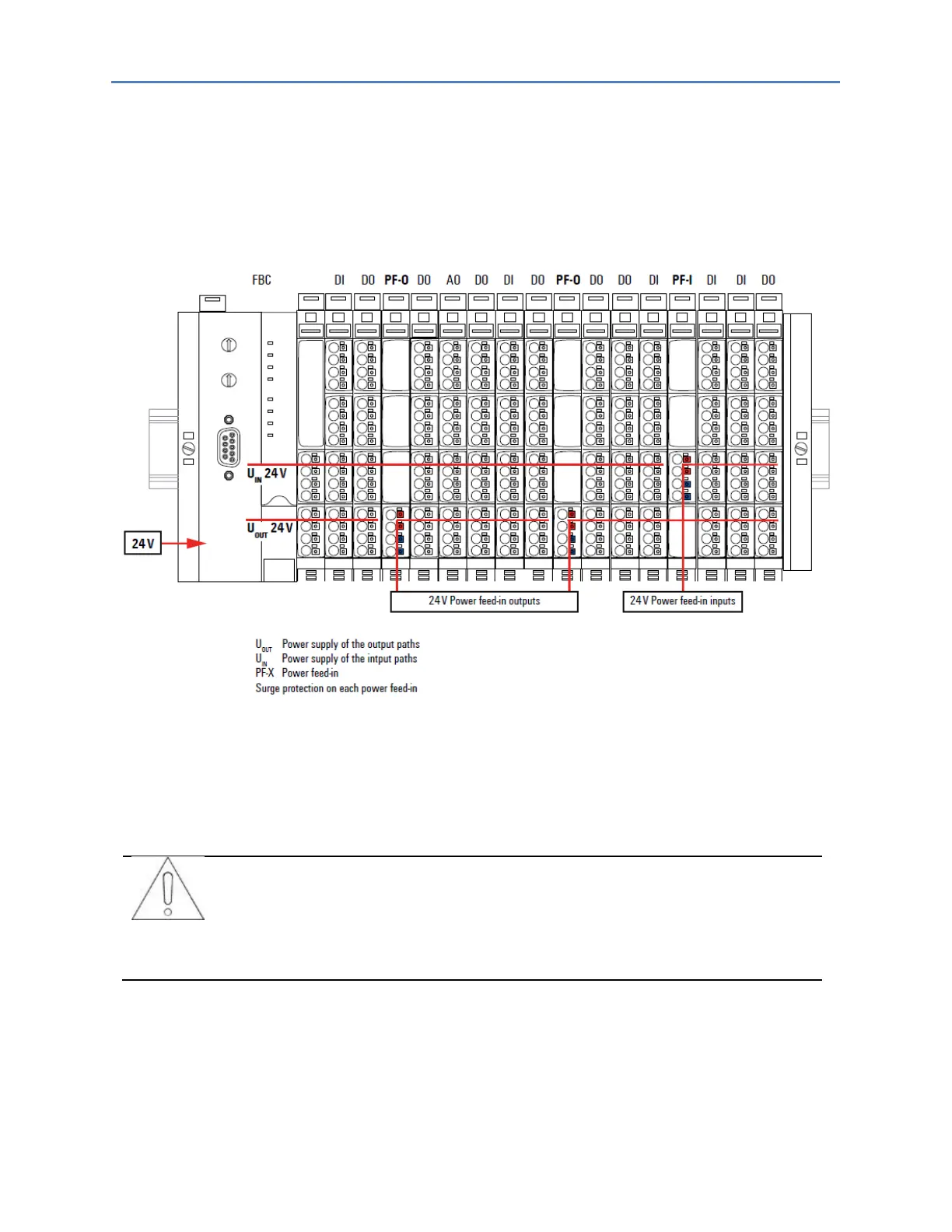
The RSTi-EP system uses three internal current paths as described in the following chapter, Detailed
Descriptions of the Fieldbus Network Adapters. Input and output paths are supplied separately, therefore a
custom-fit refreshing by power-feed modules is easily feasible.
The following figure shows the general supply concept. For detailed description and calculation of the current
demand refer to the sections, Example Calculation for the Power Supply and Calculation of Power Loss of
this manual.
3.2 Installation Distances
In order to be able to carry out the installation and subsequent maintenance work and to ensure
sufficient ventilation, the RSTi-EP station must be installed while observing the following minimum
distances (refer to the following figures).
Depending on how the station shielding is implemented, the specified
distances may have to be made larger, where necessary.
The minimum permissible conductor bending radii must also be observed. Earth terminals already
installed can be ignored when calculating the distance.

 Loading...


